Information governor
BOSCH
F 019 Z2F 447
f019z2f447
ZEXEL
105482-7140
1054827140
HINO
223002570A
223002570a
Rating:
Scheme ###:
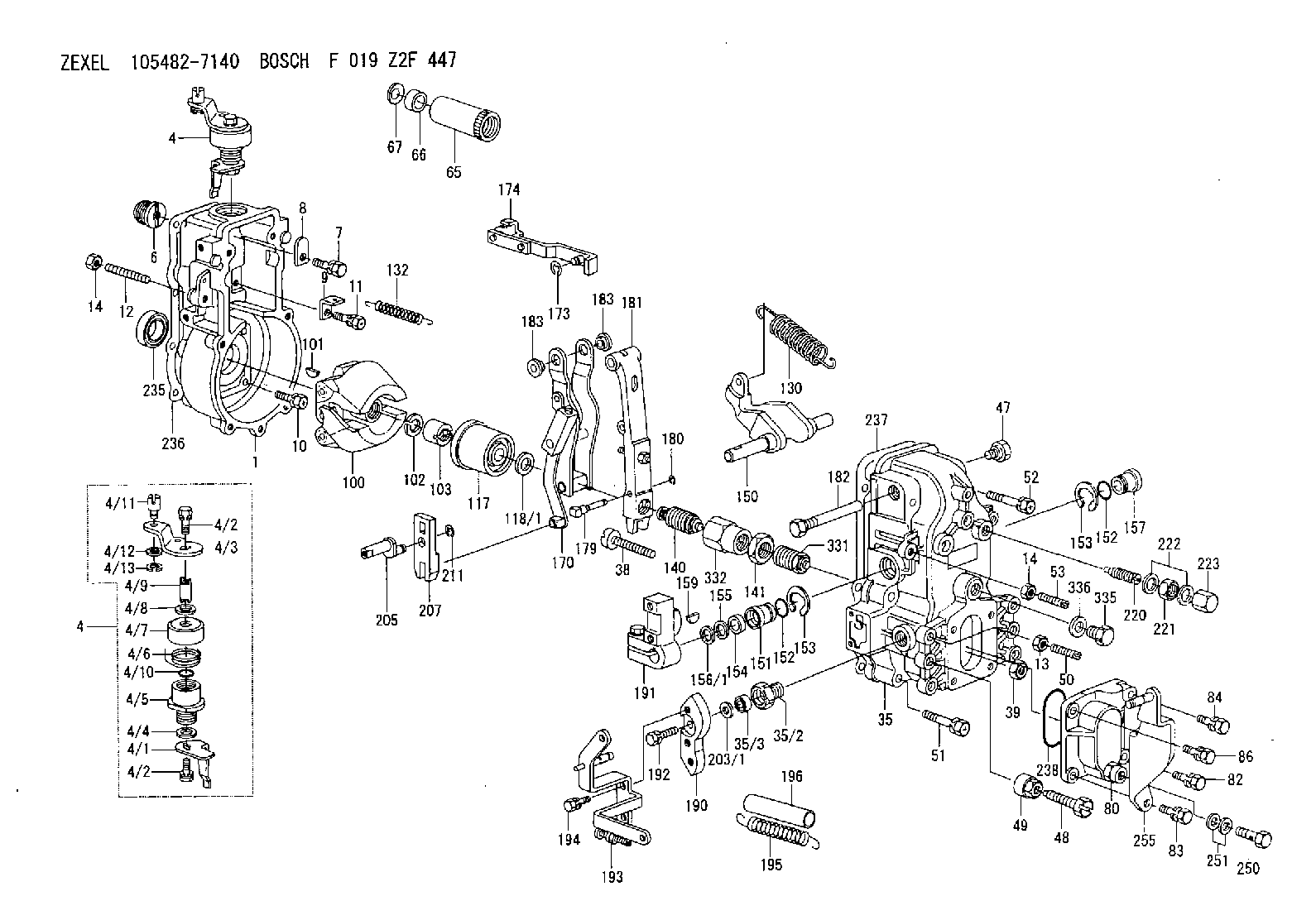
| 1. | [1] | 154000-9000 | GOVERNOR HOUSING |
| 4. | [1] | 154304-3221 | CONTROL LEVER |
| 4. | [1] | 154304-3221 | CONTROL LEVER |
| 4/1. | [1] | 154304-3200 | CONTROL LEVER |
| 4/2. | [2] | 154352-2000 | BLEEDER SCREW |
| 4/2. | [2] | 154352-2000 | BLEEDER SCREW |
| 4/3. | [1] | 154304-3300 | CONTROL LEVER |
| 4/4. | [1] | 029311-0230 | SHIM D18&10.3T0.5 |
| 4/5. | [1] | 154321-1500 | BUSHING |
| 4/6. | [1] | 154327-2300 | COILED SPRING |
| 4/7. | [1] | 154322-0100 | CAP |
| 4/8. | [1] | 029311-0220 | SHIM D18&10.3T0.2 |
| 4/9. | [1] | 154324-2700 | LEVER SHAFT |
| 4/10. | [1] | 029631-0030 | O-RING &9.8W2.3 |
| 4/11. | [1] | 154353-3701 | BEARING PIN |
| 4/12. | [1] | 014010-6140 | PLAIN WASHER D13&6.5T1 |
| 4/12B. | [0] | 029310-6040 | SHIM |
| 4/13. | [1] | 016010-0540 | LOCKING WASHER |
| 6. | [1] | 154007-0200 | ADAPTOR |
| 7. | [1] | 020018-2040 | BLEEDER SCREW M8P1.25L20 4T |
| 8. | [1] | 154353-4400 | PLATE |
| 9. | [1] | 154350-1800 | PLATE |
| 10. | [5] | 029010-6810 | BLEEDER SCREW |
| 11. | [1] | 020106-1640 | BLEEDER SCREW M6P1.0L14 |
| 12. | [1] | 154010-0200 | FLAT-HEAD SCREW |
| 13. | [1] | 029240-6010 | UNION NUT M6P1.0H5* |
| 14. | [2] | 154011-0100 | HEXAGON NUT |
| 14. | [2] | 154011-0100 | HEXAGON NUT |
| 35. | [1] | 154513-3420 | GOVERNOR COVER |
| 35/2. | [1] | 154321-1800 | BUSHING |
| 35/3. | [1] | 029621-0080 | PACKING RING |
| 38. | [1] | 154031-3500 | FLAT-HEAD SCREW |
| 39. | [1] | 154011-1600 | UNION NUT |
| 47. | [1] | 154036-0300 | CAPSULE |
| 48. | [1] | 154010-5500 | BLEEDER SCREW M10P1.25L42 |
| 49. | [1] | 154011-2100 | UNION NUT |
| 50. | [1] | 155615-1100 | FLAT-HEAD SCREW M6P1.0L37 |
| 51. | [4] | 020106-3840 | BLEEDER SCREW |
| 52. | [2] | 020106-5040 | BLEEDER SCREW |
| 53. | [1] | 154010-0100 | FLAT-HEAD SCREW |
| 65. | [1] | 155404-5520 | CAP |
| 66. | [2] | 139140-4000 | CAPSULE |
| 67. | [1] | 029141-7010 | CAPSULE |
| 80. | [1] | 154063-1020 | COVER |
| 82. | [1] | 029020-6210 | BLEEDER SCREW |
| 83. | [1] | 029020-6240 | BLEEDER SCREW |
| 84. | [1] | 029000-6800 | BLEEDER SCREW |
| 86. | [1] | 020006-2040 | BLEEDER SCREW M6P1L20 4T |
| 100. | [1] | 154100-9520 | FLYWEIGHT ASSEMBLY |
| 101. | [1] | 025803-1610 | WOODRUFF KEY |
| 102. | [1] | 029321-2020 | LOCKING WASHER |
| 103. | [1] | 029231-2030 | UNION NUT |
| 117. | [1] | 154123-0420 | SLIDING PIECE |
| 118/1. | [0] | 029311-0010 | SHIM D14&10.1T0.2 |
| 118/1. | [0] | 029311-0180 | SHIM D14&10.1T0.3 |
| 118/1. | [0] | 029311-0190 | SHIM D14&10.1T0.40 |
| 118/1. | [0] | 029311-0210 | SHIM D14&10.1T1 |
| 118/1. | [0] | 139410-0000 | SHIM D14.0&10.1T0.5 |
| 118/1. | [0] | 139410-0100 | SHIM D14.0&10.1T1.5 |
| 118/1. | [0] | 139410-3000 | SHIM D14&10.1T2.0 |
| 118/1. | [0] | 139410-3100 | SHIM D14&10.1T3.0 |
| 118/1. | [0] | 139410-3200 | SHIM D14&10.1T4.0 |
| 130. | [1] | 154150-6200 | GOVERNOR SPRING |
| 132. | [1] | 154154-1300 | COILED SPRING |
| 140. | [1] | 154178-1620 | HEADLESS SCREW |
| 141. | [1] | 029201-6220 | UNION NUT |
| 150. | [1] | 154200-3701 | SWIVELLING LEVER |
| 151. | [1] | 154204-2001 | BUSHING |
| 152. | [2] | 029631-8020 | O-RING |
| 152. | [2] | 029631-8020 | O-RING |
| 153. | [2] | 154354-3900 | LOCKING WASHER |
| 153. | [2] | 154354-3900 | LOCKING WASHER |
| 154. | [1] | 139611-0000 | PACKING RING |
| 155. | [1] | 139411-0000 | SHIM |
| 156/1. | [0] | 029311-1110 | SHIM D17&11T0.1 |
| 156/1. | [0] | 029311-1120 | SHIM D17&11T0.2 |
| 156/1. | [0] | 029311-1130 | SHIM D17&11T0.3 |
| 157. | [1] | 154204-3400 | BUSHING |
| 159. | [1] | 025803-1310 | WOODRUFF KEY |
| 170. | [1] | 154211-9420 | FORK LEVER |
| 173. | [1] | 016010-0540 | LOCKING WASHER |
| 174. | [1] | 154230-4820 | STRAP |
| 179. | [1] | 154238-0301 | BEARING PIN |
| 180. | [1] | 016010-0540 | LOCKING WASHER |
| 181. | [1] | 154236-5520 | TENSIONING LEVER |
| 182. | [1] | 154237-0900 | BEARING PIN |
| 183. | [2] | 154237-0600 | BUSHING |
| 183. | [2] | 154237-0600 | BUSHING |
| 190. | [1] | 154360-2700 | CONTROL LEVER |
| 191. | [1] | 154340-1820 | CONTROL LEVER |
| 192. | [1] | 020006-1670 | BLEEDER SCREW M6P1L16 7T |
| 193. | [1] | 154361-0521 | CONTROL LEVER |
| 194. | [2] | 020006-1240 | BLEEDER SCREW M6P1L12 4T |
| 195. | [2] | 154314-8500 | COILED SPRING |
| 196. | [2] | 154156-0600 | TUBE |
| 203/1. | [0] | 029311-0640 | SHIM D26.0&10.2T0.95 |
| 203/1. | [0] | 029311-0650 | SHIM D26.0&10.2T0.20 |
| 203/1. | [0] | 029311-0660 | SHIM D26.0&10.2T0.25 |
| 203/1. | [0] | 029311-0670 | SHIM D26.0&10.2T0.30 |
| 203/1. | [0] | 029311-0680 | SHIM D26.0&10.2T0.35 |
| 203/1. | [0] | 029311-0690 | SHIM D26.0&10.2T0.40 |
| 203/1. | [0] | 029311-0700 | SHIM D26.0&10.2T0.50 |
| 203/1. | [0] | 139410-1400 | SHIM D26&10.2T0.7 |
| 203/1. | [0] | 139410-1500 | SHIM D26&10.2T0.9 |
| 203/1. | [0] | 139410-1600 | SHIM D26&10.2T0.8 |
| 203/1. | [0] | 139410-2700 | SHIM D26&10.2T0.6 |
| 205. | [1] | 154324-3000 | LEVER SHAFT |
| 207. | [1] | 154326-0300 | CONTROL LEVER |
| 211. | [1] | 016010-0840 | LOCKING WASHER |
| 220. | [1] | 154050-3520 | HEADLESS SCREW |
| 221. | [1] | 029201-2140 | UNION NUT |
| 222. | [2] | 026512-1540 | GASKET D15.4&12.2T1.50 |
| 223. | [1] | 154159-1200 | CAP NUT |
| 235. | [1] | 029621-7010 | PACKING RING |
| 236. | [1] | 154390-1300 | GASKET |
| 237. | [1] | 154390-0300 | GASKET |
| 238. | [1] | 029635-2020 | O-RING |
| 250. | [1] | 027412-2440 | EYE BOLT |
| 251. | [2] | 139512-0100 | GASKET |
| 255. | [1] | 154213-6920 | BRACKET |
| 331. | [1] | 154176-5720 | HEADLESS SCREW |
| 332. | [1] | 029201-6010 | UNION NUT |
| 335. | [1] | 154352-2600 | CAPSULE |
| 336. | [1] | 029331-6030 | GASKET |
Cross reference number
Zexel num
Bosch num
Firm num
Name
105482-7140
F 019 Z2F 447
223002570A HINO
GOVERNOR
* K
* K
105482-7140
F 019 Z2F 447
223002640A HINO
GOVERNOR
A * K
A * K
Information:
Ejector Guide Rollers
(631 & 637)
Adjust
1. The ejector should operate freely without binding. To adjust the guide rollers, loosen the roller shaft clamping bolt. 2. Turn the roller (eccentric) shaft to position the roller. 3. Tighten the clamping bolt. Clearance between the guide rollers and the scraper bowl should be 3.00 to 20.00 mm (.118 to .787 in).Ejector Carrier Rollers
(631 & 637)
Adjust
1. The ejector should operate freely without dragging. To adjust the carrier rollers, loosen the clamping bolt. 2. Turn the roller (eccentric) shaft to position the roller.3. Tighten the clamping bolt. Clearance between the bottom of the ejector and the bottom of the bowl should be 1.0 to 13.0 mm (.04 to .50 in).Ejector Support Rollers
(631 & 637)
Adjust
1. The ejector should operate freely without dragging. To adjust the carrier rollers, loosen the clamping bolt. 2. Turn the roller (eccentric) shaft to position the roller. 3. Tighten the clamping bolt. The distance between rollers, outside to outside, should be .00 to 6.00 mm (.00 to .236 in) less than the narrowest dimension between the roller guide tracks.Refer to the Service Manual for your machine or contact your Caterpillar dealer for the correct adjustment procedure.Ejector Carriage Rollers
(639)
Adjust
Do not get under the push frame unless the front engine is stopped and the ejector floor is blocked.
1. Install pin in the position that will block movement of the carriage.See "Blocking the Ejector Floor Closed" in the "Safety" section of the Operation (Operator's) Guide. 2. The carriage should operate freely without binding. To adjust the carriage rollers, loosen the roller shaft clamping bolt. 3. Turn the roller (eccentric) shaft to position the rollers. 4. Tighten the clamping bolt. The distance between rollers, outside to outside, should be .00 to 1.50 mm (.00 to .060 in) less than the narrowest dimension between the guide tracks on the push frame.
(631 & 637)
Adjust
1. The ejector should operate freely without binding. To adjust the guide rollers, loosen the roller shaft clamping bolt. 2. Turn the roller (eccentric) shaft to position the roller. 3. Tighten the clamping bolt. Clearance between the guide rollers and the scraper bowl should be 3.00 to 20.00 mm (.118 to .787 in).Ejector Carrier Rollers
(631 & 637)
Adjust
1. The ejector should operate freely without dragging. To adjust the carrier rollers, loosen the clamping bolt. 2. Turn the roller (eccentric) shaft to position the roller.3. Tighten the clamping bolt. Clearance between the bottom of the ejector and the bottom of the bowl should be 1.0 to 13.0 mm (.04 to .50 in).Ejector Support Rollers
(631 & 637)
Adjust
1. The ejector should operate freely without dragging. To adjust the carrier rollers, loosen the clamping bolt. 2. Turn the roller (eccentric) shaft to position the roller. 3. Tighten the clamping bolt. The distance between rollers, outside to outside, should be .00 to 6.00 mm (.00 to .236 in) less than the narrowest dimension between the roller guide tracks.Refer to the Service Manual for your machine or contact your Caterpillar dealer for the correct adjustment procedure.Ejector Carriage Rollers
(639)
Adjust
Do not get under the push frame unless the front engine is stopped and the ejector floor is blocked.
1. Install pin in the position that will block movement of the carriage.See "Blocking the Ejector Floor Closed" in the "Safety" section of the Operation (Operator's) Guide. 2. The carriage should operate freely without binding. To adjust the carriage rollers, loosen the roller shaft clamping bolt. 3. Turn the roller (eccentric) shaft to position the rollers. 4. Tighten the clamping bolt. The distance between rollers, outside to outside, should be .00 to 1.50 mm (.00 to .060 in) less than the narrowest dimension between the guide tracks on the push frame.
Have questions with 105482-7140?
Group cross 105482-7140 ZEXEL
Hino
Nissan-Diesel
Hino
105482-7140
F 019 Z2F 447
223002570A
GOVERNOR
105482-7140
F 019 Z2F 447
223002640A
GOVERNOR