Information governor
BOSCH
F 019 Z1E 169
f019z1e169
ZEXEL
105472-0970
1054720970
ISUZU
1157204540
1157204540
Rating:
Scheme ###:
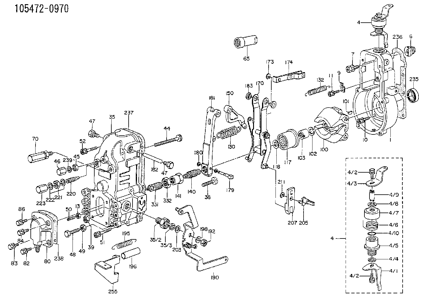
| 1. | [1] | 154000-6400 | GOVERNOR HOUSING |
| 4. | [1] | 154364-2220 | CONTROL LEVER |
| 4. | [1] | 154364-2220 | CONTROL LEVER |
| 4/1. | [1] | 154304-3500 | CONTROL LEVER |
| 4/2. | [2] | 154352-2000 | BLEEDER SCREW |
| 4/2. | [2] | 154352-2000 | BLEEDER SCREW |
| 4/3. | [1] | 154364-2200 | CONTROL LEVER |
| 4/4. | [1] | 029311-0230 | SHIM D18&10.3T0.5 |
| 4/5. | [1] | 154321-1500 | BUSHING |
| 4/6. | [1] | 154327-3500 | COILED SPRING |
| 4/7. | [1] | 154322-0100 | CAP |
| 4/8. | [1] | 029311-0220 | SHIM D18&10.3T0.2 |
| 4/9. | [1] | 154324-2700 | LEVER SHAFT |
| 4/10. | [1] | 029631-0030 | O-RING &9.8W2.3 |
| 6. | [1] | 154007-0200 | ADAPTOR |
| 7. | [1] | 020018-1840 | BLEEDER SCREW M8P1.25L18 |
| 9. | [1] | 154350-1800 | PLATE |
| 10. | [5] | 029010-6810 | BLEEDER SCREW |
| 11. | [1] | 020106-1640 | BLEEDER SCREW M6P1.0L14 |
| 13. | [1] | 029240-6010 | UNION NUT M6P1.0H5* |
| 35. | [1] | 154510-4920 | GOVERNOR COVER |
| 35/2. | [1] | 154321-1800 | BUSHING |
| 35/3. | [1] | 029621-0080 | PACKING RING |
| 38. | [1] | 154031-3200 | FLAT-HEAD SCREW |
| 39. | [1] | 154011-1600 | UNION NUT |
| 44. | [1] | 154034-0600 | FLAT-HEAD SCREW |
| 45. | [1] | 029200-8500 | UNION NUT |
| 46. | [1] | 154035-1700 | CAP NUT |
| 47. | [2] | 154036-0300 | CAPSULE |
| 47. | [2] | 154036-0300 | CAPSULE |
| 48. | [1] | 154010-2500 | BLEEDER SCREW |
| 49. | [1] | 029240-8000 | UNION NUT |
| 50. | [1] | 155615-1100 | FLAT-HEAD SCREW M6P1.0L37 |
| 51. | [4] | 020106-3840 | BLEEDER SCREW |
| 52. | [2] | 020106-5040 | BLEEDER SCREW |
| 65. | [1] | 155404-1500 | CAP |
| 70. | [1] | 154055-1020 | HEADLESS SCREW |
| 80. | [1] | 154063-2920 | COVER |
| 82. | [1] | 029020-6260 | BLEEDER SCREW |
| 83. | [1] | 020006-1640 | BLEEDER SCREW M6P1L16 4T |
| 84. | [1] | 029020-6260 | BLEEDER SCREW |
| 86. | [1] | 020006-1640 | BLEEDER SCREW M6P1L16 4T |
| 100. | [1] | 154100-9520 | FLYWEIGHT ASSEMBLY |
| 101. | [1] | 025803-1610 | WOODRUFF KEY |
| 102. | [1] | 029321-2020 | LOCKING WASHER |
| 103. | [1] | 029231-2030 | UNION NUT |
| 117. | [1] | 154123-0420 | SLIDING PIECE |
| 118/1. | [0] | 029311-0010 | SHIM D14&10.1T0.2 |
| 118/1. | [0] | 029311-0180 | SHIM D14&10.1T0.3 |
| 118/1. | [0] | 029311-0190 | SHIM D14&10.1T0.40 |
| 118/1. | [0] | 029311-0210 | SHIM D14&10.1T1 |
| 118/1. | [0] | 139410-0000 | SHIM D14.0&10.1T0.5 |
| 118/1. | [0] | 139410-0100 | SHIM D14.0&10.1T1.5 |
| 118/1. | [0] | 139410-3000 | SHIM D14&10.1T2.0 |
| 118/1. | [0] | 139410-3100 | SHIM D14&10.1T3.0 |
| 118/1. | [0] | 139410-3200 | SHIM D14&10.1T4.0 |
| 130. | [1] | 154150-2400 | GOVERNOR SPRING |
| 132. | [1] | 154154-1200 | COILED SPRING |
| 140. | [1] | 154178-5521 | HEADLESS SCREW |
| 141. | [1] | 029201-6220 | UNION NUT |
| 150. | [1] | 154200-2300 | CONTROL LEVER |
| 170. | [1] | 154216-2420 | FORK LEVER |
| 173. | [1] | 016010-0540 | LOCKING WASHER |
| 174. | [1] | 154230-4720 | STRAP |
| 181. | [1] | 154236-1120 | TENSIONING LEVER |
| 182. | [1] | 154237-0400 | BEARING PIN |
| 183. | [2] | 154237-0600 | BUSHING |
| 190. | [1] | 154362-1320 | CONTROL LEVER |
| 192. | [1] | 013020-8040 | UNION NUT M8P1.25H7 |
| 195. | [1] | 154317-0500 | COILED SPRING |
| 196. | [1] | 154156-1600 | TUBE |
| 198. | [1] | 014110-8440 | LOCKING WASHER |
| 203/1. | [0] | 029311-0640 | SHIM D26.0&10.2T0.95 |
| 203/1. | [0] | 029311-0650 | SHIM D26.0&10.2T0.20 |
| 203/1. | [0] | 029311-0660 | SHIM D26.0&10.2T0.25 |
| 203/1. | [0] | 029311-0670 | SHIM D26.0&10.2T0.30 |
| 203/1. | [0] | 029311-0680 | SHIM D26.0&10.2T0.35 |
| 203/1. | [0] | 029311-0690 | SHIM D26.0&10.2T0.40 |
| 203/1. | [0] | 029311-0700 | SHIM D26.0&10.2T0.50 |
| 203/1. | [0] | 139410-1400 | SHIM D26&10.2T0.7 |
| 203/1. | [0] | 139410-1500 | SHIM D26&10.2T0.9 |
| 203/1. | [0] | 139410-1600 | SHIM D26&10.2T0.8 |
| 203/1. | [0] | 139410-2700 | SHIM D26&10.2T0.6 |
| 205. | [1] | 154324-1200 | LEVER SHAFT |
| 207. | [1] | 154326-0300 | CONTROL LEVER |
| 211. | [1] | 016010-0840 | LOCKING WASHER |
| 220. | [1] | 154050-1220 | HEADLESS SCREW |
| 221. | [1] | 029201-2140 | UNION NUT |
| 222. | [2] | 139512-0000 | GASKET D17.2&12.2T1.0 |
| 223. | [1] | 154159-1200 | CAP NUT |
| 236. | [1] | 154390-0000 | GASKET |
| 237. | [1] | 154390-0300 | GASKET |
| 238. | [1] | 154390-4300 | GASKET |
| 239. | [1] | 026508-1240 | GASKET D11.9&8.2T1 |
| 255. | [1] | 154356-5120 | BRACKET |
| 331. | [1] | 154172-3420 | HEADLESS SCREW |
| 332. | [1] | 029201-6010 | UNION NUT |
| 350. | [1] | 154359-4200 | CAP |
Include in #1:
101601-7550
as GOVERNOR
Cross reference number
Zexel num
Bosch num
Firm num
Name
105472-0970
1157204540 ISUZU
GOVERNOR
* K 14JL MECHANICAL GOVERNOR GOV RAD GOV
* K 14JL MECHANICAL GOVERNOR GOV RAD GOV
Information:
TERMINATION DATE
31Jan2012
PROBLEM
The existing fuel injection pump can fail on certain CP-533E and CS-533E Vibratory Soil Compactors. If the existing fuel injection pump fails it can cause low power, poor starting, fuel leaks, and engine performance issues.
AFFECTED PRODUCT
Model Identification Number
CP-533E ASM00310-00311, 313, 316-380
BZG00466-01134
TLH00101-00147
CS-533E ASL03060, 3068, 3092, 3103, 3106, 3110, 3121, 3125-3126, 3130-3135, 3138-3872
BZE01120-02370
TBE00148-00237
TJL00100-01472, 1474-1628, 1630-1631, 1633-1637, 1639-1678
PARTS NEEDED
Qty
Part Number Description
1 2845000 PUMP GP-F INJ -B
In order to allow equitable parts availability to all participating dealers, please limit your initial parts order to not exceed 1% of dealership population. This is an initial order recommendation only, and the ultimate responsibility for ordering the total number of parts needed to satisfy the program lies with the dealer.
ACTION REQUIRED
Replace the failed fuel injection pump. Refer to the engine's Disassembly and Assembly, "Fuel Injection Pump - Remove and Install".
While carrying out "Fuel Injection Pump - Remove", please ensure that the fuel injection pump gear backlash is removed and the fuel injection pump locking bolt is tightened to a torque of 17 N.m (13 lb ft).
Fuel injection pumps that have not been locked correctly will have the claim rejected or debited.
After the new fuel injection pump has been installed, carry out checks for air in the fuel. Refer to the engine's Testing and Adjusting, "Air in Fuel - Test".
To ensure correct priming of the fuel system on first start-up, follow the procedure below.
1. Ensure that all low pressure fuel connections and high pressure fuel lines are installed correctly.
2. Turn the ignition key to the RUN position. Leave the ignition key in the RUN position for three minutes.
3. Crank the engine with the throttle lever in the CLOSED position until the engine starts.
Note: If necessary, loosen the union nuts on the fuel injection lines at the connection with the fuel injector until fuel is evident. Stop cranking the engine. Tighten the union nuts to a torque of 30 N.m (22 lb ft).
4. Start the engine and run the engine at low idle for one minute.
5. Cycle the throttle lever from the low idle position to the high idle position three times. The cycle time for the throttle lever is one second to six seconds for one complete cycle.
6. Check for leaks in the fuel system.
DOCUMENTATION PROCEDURE
Please ensure that when submitting the claim the following documentation is provided. If the requested documentation is not provided, the claim may be rejected or debited.
1. Full details of the customer?s complaint and the symptoms witnessed.
2. Test work and checks carried out to diagnose that the fuel injection pump is the part causing failure.
3. Results from the Testing and Adjusting, "Air in Fuel - Test". Please include photos of any air seen in the SIMS entry.
SERVICE CLAIM ALLOWANCES
Product smu/age whichever comes first Caterpillar Dealer Suggested Customer Suggested
Parts % Labor Hrs% Parts % Labor Hrs% Parts % Labor Hrs%
0-3000 hrs,
0-36 mo 100.0% 100.0% 0.0% 0.0% 0.0% 0.0%
This is a 4.0-hour job
PARTS DISPOSITION
***** NACD *****
Hold all failed fuel injection pumps for a Parts Return Request (PRR). A PRR will be issued to you through the