Information governor
BOSCH
9 420 614 683
9420614683
ZEXEL
105472-0910
1054720910
Rating:
Scheme ###:
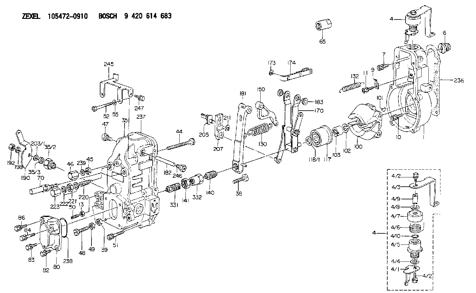
| 1. | [1] | 154000-6400 | GOVERNOR HOUSING |
| 4. | [1] | 154304-1220 | CONTROL LEVER |
| 4. | [1] | 154304-1220 | CONTROL LEVER |
| 4/1. | [1] | 154304-3500 | CONTROL LEVER |
| 4/2. | [2] | 154352-2000 | BLEEDER SCREW |
| 4/2. | [2] | 154352-2000 | BLEEDER SCREW |
| 4/3. | [1] | 154304-1200 | CONTROL LEVER |
| 4/4. | [1] | 029311-0230 | SHIM D18&10.3T0.5 |
| 4/5. | [1] | 154321-1500 | BUSHING |
| 4/6. | [1] | 154327-3500 | COILED SPRING |
| 4/7. | [1] | 154322-0100 | CAP |
| 4/8. | [1] | 029311-0220 | SHIM D18&10.3T0.2 |
| 4/9. | [1] | 154324-2700 | LEVER SHAFT |
| 4/10. | [1] | 029631-0030 | O-RING &9.8W2.3 |
| 6. | [1] | 154007-0200 | ADAPTOR |
| 7. | [1] | 020018-1840 | BLEEDER SCREW M8P1.25L18 |
| 9. | [1] | 154350-1800 | PLATE |
| 10. | [5] | 029010-6810 | BLEEDER SCREW |
| 11. | [1] | 020106-1640 | BLEEDER SCREW M6P1.0L14 |
| 13. | [1] | 029240-6010 | UNION NUT M6P1.0H5* |
| 35. | [1] | 154510-4320 | GOVERNOR COVER |
| 35/2. | [1] | 154321-1800 | BUSHING |
| 35/3. | [1] | 029621-0080 | PACKING RING |
| 38. | [1] | 154031-3200 | FLAT-HEAD SCREW |
| 39. | [1] | 154011-1600 | UNION NUT |
| 44. | [1] | 154034-0600 | FLAT-HEAD SCREW |
| 45. | [1] | 029200-8500 | UNION NUT |
| 46. | [1] | 154035-1700 | CAP NUT |
| 47. | [1] | 154036-0300 | CAPSULE |
| 48. | [1] | 154010-2500 | BLEEDER SCREW |
| 49. | [1] | 029240-8000 | UNION NUT |
| 50. | [1] | 155615-1000 | FLAT-HEAD SCREW |
| 51. | [4] | 020106-3840 | BLEEDER SCREW |
| 52. | [2] | 029010-6850 | BLEEDER SCREW |
| 55. | [2] | 014110-6440 | LOCKING WASHER |
| 65. | [1] | 155404-3600 | CAP |
| 70. | [1] | 154055-0120 | HEADLESS SCREW |
| 80. | [1] | 154060-7900 | COVER |
| 82. | [1] | 020006-1640 | BLEEDER SCREW M6P1L16 4T |
| 83. | [1] | 029020-6210 | BLEEDER SCREW |
| 84. | [1] | 029000-6800 | BLEEDER SCREW |
| 86. | [1] | 029020-6210 | BLEEDER SCREW |
| 100. | [1] | 154100-5020 | FLYWEIGHT ASSEMBLY |
| 101. | [1] | 025803-1610 | WOODRUFF KEY |
| 102. | [1] | 029321-2020 | LOCKING WASHER |
| 103. | [1] | 029231-2030 | UNION NUT |
| 117. | [1] | 154123-0420 | SLIDING PIECE |
| 118/1. | [0] | 029311-0010 | SHIM D14&10.1T0.2 |
| 118/1. | [0] | 029311-0180 | SHIM D14&10.1T0.3 |
| 118/1. | [0] | 029311-0190 | SHIM D14&10.1T0.40 |
| 118/1. | [0] | 029311-0210 | SHIM D14&10.1T1 |
| 118/1. | [0] | 139410-0000 | SHIM D14.0&10.1T0.5 |
| 118/1. | [0] | 139410-0100 | SHIM D14.0&10.1T1.5 |
| 118/1. | [0] | 139410-3000 | SHIM D14&10.1T2.0 |
| 118/1. | [0] | 139410-3100 | SHIM D14&10.1T3.0 |
| 118/1. | [0] | 139410-3200 | SHIM D14&10.1T4.0 |
| 130. | [1] | 154150-2400 | GOVERNOR SPRING |
| 132. | [1] | 154154-1300 | COILED SPRING |
| 140. | [1] | 154175-8920 | HEADLESS SCREW |
| 141. | [1] | 029201-6220 | UNION NUT |
| 150. | [1] | 154200-2300 | CONTROL LEVER |
| 170. | [1] | 154211-3520 | FORK LEVER |
| 173. | [1] | 016010-0540 | LOCKING WASHER |
| 174. | [1] | 154230-4720 | STRAP |
| 181. | [1] | 154236-1220 | TENSIONING LEVER |
| 182. | [1] | 154237-0400 | BEARING PIN |
| 183. | [2] | 154237-0600 | BUSHING |
| 190. | [1] | 154306-1400 | CONTROL LEVER |
| 192. | [1] | 013020-8040 | UNION NUT M8P1.25H7 |
| 198. | [1] | 014110-8440 | LOCKING WASHER |
| 203/1. | [0] | 029311-0640 | SHIM D26.0&10.2T0.95 |
| 203/1. | [0] | 029311-0650 | SHIM D26.0&10.2T0.20 |
| 203/1. | [0] | 029311-0660 | SHIM D26.0&10.2T0.25 |
| 203/1. | [0] | 029311-0670 | SHIM D26.0&10.2T0.30 |
| 203/1. | [0] | 029311-0680 | SHIM D26.0&10.2T0.35 |
| 203/1. | [0] | 029311-0690 | SHIM D26.0&10.2T0.40 |
| 203/1. | [0] | 029311-0700 | SHIM D26.0&10.2T0.50 |
| 203/1. | [0] | 139410-1400 | SHIM D26&10.2T0.7 |
| 203/1. | [0] | 139410-1500 | SHIM D26&10.2T0.9 |
| 203/1. | [0] | 139410-1600 | SHIM D26&10.2T0.8 |
| 203/1. | [0] | 139410-2700 | SHIM D26&10.2T0.6 |
| 205. | [1] | 154324-1200 | LEVER SHAFT |
| 207. | [1] | 154326-0300 | CONTROL LEVER |
| 211. | [1] | 016010-0840 | LOCKING WASHER |
| 220. | [1] | 154050-0920 | HEADLESS SCREW |
| 221. | [1] | 029201-2140 | UNION NUT |
| 222. | [2] | 026512-1540 | GASKET D15.4&12.2T1.50 |
| 223. | [1] | 154159-1200 | CAP NUT |
| 236. | [1] | 154390-0000 | GASKET |
| 237. | [1] | 154390-0300 | GASKET |
| 238. | [1] | 029635-2020 | O-RING |
| 239. | [1] | 026508-1240 | GASKET D11.9&8.2T1 |
| 245. | [1] | 154316-9000 | BRACKET |
| 246. | [1] | 154036-1200 | CAPSULE |
| 247. | [1] | 020006-1240 | BLEEDER SCREW M6P1L12 4T |
| 331. | [1] | 154179-0220 | HEADLESS SCREW |
| 332. | [1] | 029201-6010 | UNION NUT |
Include in #1:
101682-9330
as GOVERNOR
Cross reference number
Zexel num
Bosch num
Firm num
Name
105472-0910
GOVERNOR
K 14JL MECHANICAL GOVERNOR GOV RAD GOV
K 14JL MECHANICAL GOVERNOR GOV RAD GOV
Information:
Introduction
1. Type 2 fuel injector. 2. Two piece follower. 3. Nose cone. 4. Nozzle assembly.Tools are now available for the removal and installation of nose cone (3), on type 2 fuel injectors (1), when it is necessary to replace a nozzle assembly (4). Type 2 fuel injectors can be identified by the two piece follower (2).
5. 1U9395 Plate. 6. 1U8701 Socket.Use 1U9395 Plate (5) with the 6V4830 Fixture Group (not shown) and the procedure given in this instruction, for the removal and installation of nozzle assembly (4).Earlier type 2 injectors have a nose cone that has serrations on its exterior. These serrations will be damaged when the nose cone is removed. A damaged nose cone is not to be used again. A 7C9795 Nose Cone is available for use as a replacement for the original nose cone.The 7C9795 Nose Cone has a hexagon shape on its exterior. This nose cone can be installed and tightened using 1U8701 Socket (6). When the 7C9795 Nose Cone is installed, be sure to tighten it according to the procedure given in this instruction.Removal and Installation of Nose Cone and Nozzle Assembly
1. Remove the original plate from the 6V4830 Fixture Group and install 1U9395 Plate (1).2. Put injector (2) in position on the fixture group. If the exterior of the injector nose cone is a hexagon shape as shown at location (A), use the 1U8701 Socket for nose cone removal. 3. If the exterior of the nose cone has serrations as shown at location (B), use a pipe wrench, as shown, to remove the nose cone. Anytime a pipe wrench is used to remove a nose cone, the nose cone will be damaged. Never use or install a damaged nose cone on an injector. Always install a new 7C9795 Nose Cone as a replacement. 4. After the nose cone has been loosened, use a hammer and 6V4822 Tip Driver (3) to tap the nozzle assembly as shown. This is done to break the connection between the nozzle assembly and the nose cone. Be sure to use only the 6V4822 Tip Driver in this procedure, because use of a standard punch, or any other similar tool will cause damage to the nozzle tip.5. Remove the nose cone and nozzle assembly. 6. Inspect surface (C) in the injector. This is the sealing surface for the nozzle assembly. This surface must be clean and free of any scratches, nicks or burrs. Even a piece of lint from a shop towel can cause a leak and destroy nozzle performance. 7. Remove original O-ring seal (4). Install a new O-ring seal, refer to the Parts Book for the correct part number. Make sure the O-ring seal is not damaged during installation.Use a generous amount of 1P0808 Grease, or a good grade of multi-purpose lubricant, to lubricate the O-ring seal before the nose cone is installed.8. Install new nozzle assembly (5) on the injector. 9. Install and finger tighten the new 7C9795 Nose Cone on the injector. Using a