Information governor
BOSCH
F 019 Z2F 390
f019z2f390
ZEXEL
105470-1390
1054701390
Rating:
Scheme ###:
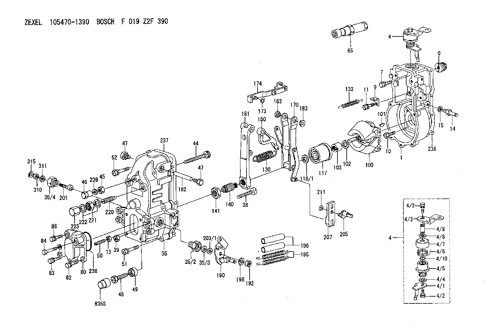
| 1. | [1] | 154000-6400 | GOVERNOR HOUSING |
| 4. | [1] | 154365-7420 | CONTROL LEVER |
| 4. | [1] | 154365-7420 | CONTROL LEVER |
| 4/1. | [1] | 154304-3500 | CONTROL LEVER |
| 4/2. | [2] | 154352-2000 | BLEEDER SCREW |
| 4/2. | [2] | 154352-2000 | BLEEDER SCREW |
| 4/3. | [1] | 154365-7400 | CONTROL LEVER |
| 4/4. | [1] | 029311-0230 | SHIM D18&10.3T0.5 |
| 4/5. | [1] | 154321-1500 | BUSHING |
| 4/6. | [1] | 154327-3500 | COILED SPRING |
| 4/7. | [1] | 154322-0100 | CAP |
| 4/8. | [1] | 029311-0220 | SHIM D18&10.3T0.2 |
| 4/9. | [1] | 154324-2700 | LEVER SHAFT |
| 4/10. | [1] | 029631-0030 | O-RING &9.8W2.3 |
| 6. | [1] | 154007-0200 | ADAPTOR |
| 7. | [1] | 020018-1840 | BLEEDER SCREW M8P1.25L18 |
| 9. | [1] | 154350-1800 | PLATE |
| 10. | [5] | 029010-6810 | BLEEDER SCREW |
| 11. | [1] | 020106-1640 | BLEEDER SCREW M6P1.0L14 |
| 13. | [1] | 029240-6010 | UNION NUT M6P1.0H5* |
| 14. | [1] | 154352-3020 | BLEEDER SCREW |
| 15. | [1] | 014110-8440 | LOCKING WASHER |
| 35. | [1] | 154510-8620 | GOVERNOR COVER |
| 35/2. | [1] | 154321-1800 | BUSHING |
| 35/3. | [1] | 029621-0080 | PACKING RING |
| 35/4. | [1] | 154321-2400 | BUSHING |
| 38. | [1] | 154031-3200 | FLAT-HEAD SCREW |
| 39. | [1] | 154011-1600 | UNION NUT |
| 44. | [1] | 154034-2300 | FLAT-HEAD SCREW |
| 45. | [1] | 154011-2500 | UNION NUT |
| 46. | [1] | 154035-2100 | CAP NUT |
| 47. | [2] | 154036-0300 | CAPSULE |
| 47. | [2] | 154036-0300 | CAPSULE |
| 48. | [1] | 154010-4400 | BLEEDER SCREW |
| 49. | [1] | 029240-8000 | UNION NUT |
| 50. | [1] | 155615-1000 | FLAT-HEAD SCREW |
| 51. | [4] | 020106-3840 | BLEEDER SCREW |
| 52. | [2] | 020106-5040 | BLEEDER SCREW |
| 65. | [1] | 153043-4520 | STOPPING DEVICE |
| 80. | [1] | 154060-0020 | COVER |
| 82. | [1] | 029020-6210 | BLEEDER SCREW |
| 83. | [1] | 020006-1640 | BLEEDER SCREW M6P1L16 4T |
| 84. | [1] | 029020-6220 | BLEEDER SCREW |
| 85. | [1] | 014110-6440 | LOCKING WASHER |
| 86. | [1] | 020006-1640 | BLEEDER SCREW M6P1L16 4T |
| 100. | [1] | 154100-4020 | FLYWEIGHT ASSEMBLY |
| 101. | [1] | 025803-1610 | WOODRUFF KEY |
| 102. | [1] | 029321-2020 | LOCKING WASHER |
| 103. | [1] | 029231-2030 | UNION NUT |
| 117. | [1] | 154123-1420 | SLIDING PIECE |
| 118/1. | [0] | 029311-0010 | SHIM D14&10.1T0.2 |
| 118/1. | [0] | 029311-0180 | SHIM D14&10.1T0.3 |
| 118/1. | [0] | 029311-0190 | SHIM D14&10.1T0.40 |
| 118/1. | [0] | 029311-0210 | SHIM D14&10.1T1 |
| 118/1. | [0] | 139410-0000 | SHIM D14.0&10.1T0.5 |
| 118/1. | [0] | 139410-0100 | SHIM D14.0&10.1T1.5 |
| 118/1. | [0] | 139410-3000 | SHIM D14&10.1T2.0 |
| 118/1. | [0] | 139410-3100 | SHIM D14&10.1T3.0 |
| 118/1. | [0] | 139410-3200 | SHIM D14&10.1T4.0 |
| 130. | [1] | 154150-2400 | GOVERNOR SPRING |
| 132. | [1] | 154154-1300 | COILED SPRING |
| 140. | [1] | 154176-2720 | HEADLESS SCREW |
| 141. | [1] | 029201-6010 | UNION NUT |
| 150. | [1] | 154200-2300 | CONTROL LEVER |
| 170. | [1] | 154216-9720 | FORK LEVER |
| 173. | [1] | 016010-0540 | LOCKING WASHER |
| 174. | [1] | 154230-4720 | STRAP |
| 181. | [1] | 154236-1120 | TENSIONING LEVER |
| 182. | [1] | 154237-0400 | BEARING PIN |
| 183. | [2] | 154237-0600 | BUSHING |
| 183. | [2] | 154237-0600 | BUSHING |
| 190. | [1] | 154305-6120 | CONTROL LEVER |
| 192. | [1] | 013020-8040 | UNION NUT M8P1.25H7 |
| 195. | [2] | 154332-1800 | COILED SPRING |
| 196. | [2] | 154156-0600 | TUBE |
| 198. | [1] | 014110-8440 | LOCKING WASHER |
| 201. | [1] | 154324-3720 | LEVER SHAFT |
| 203/1. | [0] | 029311-0640 | SHIM D26.0&10.2T0.95 |
| 203/1. | [0] | 029311-0650 | SHIM D26.0&10.2T0.20 |
| 203/1. | [0] | 029311-0660 | SHIM D26.0&10.2T0.25 |
| 203/1. | [0] | 029311-0670 | SHIM D26.0&10.2T0.30 |
| 203/1. | [0] | 029311-0680 | SHIM D26.0&10.2T0.35 |
| 203/1. | [0] | 029311-0690 | SHIM D26.0&10.2T0.40 |
| 203/1. | [0] | 029311-0700 | SHIM D26.0&10.2T0.50 |
| 203/1. | [0] | 139410-1400 | SHIM D26&10.2T0.7 |
| 203/1. | [0] | 139410-1500 | SHIM D26&10.2T0.9 |
| 203/1. | [0] | 139410-1600 | SHIM D26&10.2T0.8 |
| 203/1. | [0] | 139410-2700 | SHIM D26&10.2T0.6 |
| 205. | [1] | 154324-1200 | LEVER SHAFT |
| 207. | [1] | 154326-0300 | CONTROL LEVER |
| 211. | [1] | 016010-0840 | LOCKING WASHER |
| 220. | [1] | 154050-1220 | HEADLESS SCREW |
| 221. | [1] | 029201-2140 | UNION NUT |
| 222. | [2] | 139512-0000 | GASKET D17.2&12.2T1.0 |
| 223. | [1] | 154159-1200 | CAP NUT |
| 236. | [1] | 154390-0000 | GASKET |
| 237. | [1] | 154390-0300 | GASKET |
| 238. | [1] | 029635-2020 | O-RING |
| 239. | [1] | 026508-1240 | GASKET D11.9&8.2T1 |
| 310. | [1] | 013010-6040 | UNION NUT M6P1H5 |
| 311. | [1] | 014110-6440 | LOCKING WASHER |
| 315. | [1] | 154357-5700 | CAP |
| 835S. | [1] | 154062-1700 | CAP D20L32 |
Include in #1:
101603-0110
as GOVERNOR
Cross reference number
Zexel num
Bosch num
Firm num
Name
105470-1390
F 019 Z2F 390
GOVERNOR
* K
* K
Information:
Determination Of Overhaul Timing
Generally, the engine needs an overhaul when the compression pressure of the engine becomes low, and the amounts of engine oil consumption and blow-by gas increase.Reduced power output, increased fuel consumption, low oil pressure, difficult in starting, and increased operating noise are also signs that suggest the need for an overhaul; however, since these problems can be caused by various factors, they do not serve as reliable criteria for determining the need for an overhaul.Reduced compression pressure manifests a variety of symptoms, thus making it difficult to accurately determine when the engine needs an overhaul. The following shows typical problems caused by reduced compression pressure.(1) Decreased output power(2) Increased fuel consumption(3) Increased engine oil consumption(4) Increased blow-by gas from breather due to leakage of combustion gas through worn cylinder liners and piston rings(5) Increased gas leakage due to poor seating of inlet and exhaust valves(6) Difficulty in starting(7) Increased noise from engine parts(8) Abnormal exhaust color after warm-up operationThe engine can exhibit these conditions in various combinations.Some of the problems are directly caused by worn engine parts, while others are not.Phenomena described in (2) and (6) can also result from improper injection volume, incorrect fuel injection timing, worn plungers, defective nozzles, and faulty conditions of electrical devices such as battery, starter and alternator.The most valid reason to overhaul an engine is a decrease in the compression pressure due to worn cylinder liners and pistons, as described in (4), and once this is determined, other symptoms should be taken into consideration in order to make the final judgement of whether the engine needs an overhaul.Measurement of Compression Pressure
Preparation For Inspection
Check the following before inspection.(1) Make sure that the engine oil, air cleaner, starter, battery, etc. are in normal operating condition.Inspection
(1) Move the control lever to the STOP position.(2) Remove the glow plugs from all cylinders, and attach the gage adapter and compression gage to the cylinder to be tested. (3) Crank the engine with the starter, and read the compression gage indication when the indication stabilizes.(4) If the measured compression pressure is lower than the limit, consider overhauling the engine.
(a) Measure the compression pressure in all cylinders.(b) As compression pressure varies with the engine speed, measure the engine speed at the same time.
Measure the compression pressure while the engine is running at 150 to 200 min-1. The oil and coolant temperatures should be between 20 and 30 °C [68 and 86°F].
(a) Measure the compression pressure at regular intervals and keep the record of changes in compression pressure.(b) Compression pressure will be slightly higher when the engine is new or immediately after an overhaul due to tight clearances of piston rings and valve seats, but it decreases to the standard level after the parts break in.
Preparation For Disassembly
Removing Electrical Wiring
Removing electrical wiringDisconnect harness and wires from the following devices.Before disconnecting, attach tags or other indications on the terminals to facilitate reconnection.* Starter* SwitchesDraining Coolant
Draining coolantLoosen the coolant drain plug on the right-hand side of the cylinder block
Have questions with 105470-1390?
Group cross 105470-1390 ZEXEL
Isuzu
105470-1390
F 019 Z2F 390
GOVERNOR