Information governor
BOSCH
F 019 Z1E 162
f019z1e162
ZEXEL
105470-0800
1054700800
ISUZU
5157200701
5157200701
Rating:
Scheme ###:
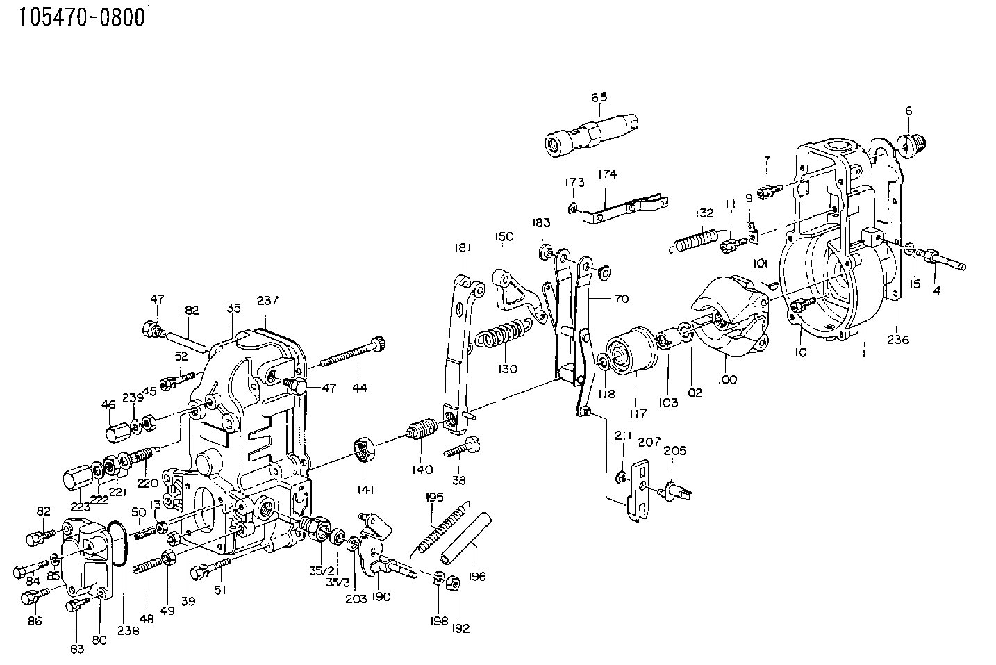
| 1. | [1] | 154000-7800 | GOVERNOR HOUSING |
| 6. | [1] | 154007-0200 | ADAPTOR |
| 7. | [1] | 020018-1840 | BLEEDER SCREW M8P1.25L18 |
| 9. | [1] | 154350-1800 | PLATE |
| 10. | [5] | 029010-6810 | BLEEDER SCREW |
| 11. | [1] | 020106-1640 | BLEEDER SCREW M6P1.0L14 |
| 13. | [1] | 029240-6010 | UNION NUT M6P1.0H5* |
| 14. | [1] | 154352-3020 | BLEEDER SCREW |
| 15. | [1] | 014110-8440 | LOCKING WASHER |
| 35. | [1] | 154510-2120 | GOVERNOR COVER |
| 35/2. | [1] | 154321-1800 | BUSHING |
| 35/3. | [1] | 029621-0080 | PACKING RING |
| 38. | [1] | 154031-3200 | FLAT-HEAD SCREW |
| 39. | [1] | 154011-1600 | UNION NUT |
| 44. | [1] | 154034-0600 | FLAT-HEAD SCREW |
| 45. | [1] | 029200-8500 | UNION NUT |
| 46. | [1] | 154035-1700 | CAP NUT |
| 47. | [2] | 154036-0300 | CAPSULE |
| 47. | [2] | 154036-0300 | CAPSULE |
| 48. | [1] | 154010-4400 | BLEEDER SCREW |
| 49. | [1] | 029240-8000 | UNION NUT |
| 50. | [1] | 155615-1000 | FLAT-HEAD SCREW |
| 51. | [4] | 020106-3840 | BLEEDER SCREW |
| 52. | [2] | 020106-5040 | BLEEDER SCREW |
| 65. | [1] | 153043-4520 | STOPPING DEVICE |
| 80. | [1] | 154060-7900 | COVER |
| 82. | [1] | 029020-6210 | BLEEDER SCREW |
| 83. | [1] | 020006-1640 | BLEEDER SCREW M6P1L16 4T |
| 84. | [1] | 029020-6220 | BLEEDER SCREW |
| 85. | [1] | 014110-6440 | LOCKING WASHER |
| 86. | [1] | 020006-1640 | BLEEDER SCREW M6P1L16 4T |
| 100. | [1] | 154100-4020 | FLYWEIGHT ASSEMBLY |
| 101. | [1] | 025803-1610 | WOODRUFF KEY |
| 102. | [1] | 029321-2020 | LOCKING WASHER |
| 103. | [1] | 029231-2030 | UNION NUT |
| 117. | [1] | 154123-1420 | SLIDING PIECE |
| 118/1. | [0] | 029311-0010 | SHIM D14&10.1T0.2 |
| 118/1. | [0] | 029311-0180 | SHIM D14&10.1T0.3 |
| 118/1. | [0] | 029311-0190 | SHIM D14&10.1T0.40 |
| 118/1. | [0] | 029311-0210 | SHIM D14&10.1T1 |
| 118/1. | [0] | 139410-0000 | SHIM D14.0&10.1T0.5 |
| 118/1. | [0] | 139410-0100 | SHIM D14.0&10.1T1.5 |
| 118/1. | [0] | 139410-3000 | SHIM D14&10.1T2.0 |
| 118/1. | [0] | 139410-3100 | SHIM D14&10.1T3.0 |
| 118/1. | [0] | 139410-3200 | SHIM D14&10.1T4.0 |
| 130. | [1] | 154150-2400 | GOVERNOR SPRING |
| 132. | [1] | 154154-1300 | COILED SPRING |
| 140. | [1] | 154176-2720 | HEADLESS SCREW |
| 141. | [1] | 029201-6010 | UNION NUT |
| 150. | [1] | 154200-2300 | CONTROL LEVER |
| 170. | [1] | 154211-0520 | FORK LEVER |
| 173. | [1] | 016010-0540 | LOCKING WASHER |
| 174. | [1] | 154230-3920 | STRAP |
| 181. | [1] | 154236-1120 | TENSIONING LEVER |
| 182. | [1] | 154237-0400 | BEARING PIN |
| 183. | [2] | 154237-0600 | BUSHING |
| 190. | [1] | 154305-6120 | CONTROL LEVER |
| 192. | [1] | 013020-8040 | UNION NUT M8P1.25H7 |
| 195. | [2] | 154332-1800 | COILED SPRING |
| 196. | [2] | 154156-0600 | TUBE |
| 198. | [1] | 014110-8440 | LOCKING WASHER |
| 203/1. | [0] | 029311-0640 | SHIM D26.0&10.2T0.95 |
| 203/1. | [0] | 029311-0650 | SHIM D26.0&10.2T0.20 |
| 203/1. | [0] | 029311-0660 | SHIM D26.0&10.2T0.25 |
| 203/1. | [0] | 029311-0670 | SHIM D26.0&10.2T0.30 |
| 203/1. | [0] | 029311-0680 | SHIM D26.0&10.2T0.35 |
| 203/1. | [0] | 029311-0690 | SHIM D26.0&10.2T0.40 |
| 203/1. | [0] | 029311-0700 | SHIM D26.0&10.2T0.50 |
| 203/1. | [0] | 139410-1400 | SHIM D26&10.2T0.7 |
| 203/1. | [0] | 139410-1500 | SHIM D26&10.2T0.9 |
| 203/1. | [0] | 139410-1600 | SHIM D26&10.2T0.8 |
| 203/1. | [0] | 139410-2700 | SHIM D26&10.2T0.6 |
| 205. | [1] | 154324-1200 | LEVER SHAFT |
| 207. | [1] | 154326-0300 | CONTROL LEVER |
| 211. | [1] | 016010-0840 | LOCKING WASHER |
| 220. | [1] | 154050-1220 | HEADLESS SCREW |
| 221. | [1] | 029201-2140 | UNION NUT |
| 222. | [2] | 139512-0000 | GASKET D17.2&12.2T1.0 |
| 223. | [1] | 154159-1200 | CAP NUT |
| 236. | [1] | 154390-0000 | GASKET |
| 237. | [1] | 154390-0300 | GASKET |
| 238. | [1] | 029635-2020 | O-RING |
| 239. | [1] | 026508-1240 | GASKET D11.9&8.2T1 |
Cross reference number
Zexel num
Bosch num
Firm num
Name
105470-0800
5157200701 ISUZU
GOVERNOR
K 14JL MECHANICAL GOVERNOR GOV RAD GOV
K 14JL MECHANICAL GOVERNOR GOV RAD GOV
Information:
Starting System
Use a D.C. voltmeter to locate starting system components which do not function.Move starting control switch to energize the starter solenoid. Starter solenoid operation is audible as the starter motor pinion engages with the ring gear on the engine flywheel. The solenoid operation should also close the electric circuit to the motor. Attach one voltmeter lead to the solenoid terminal that is connected to the motor. Ground the other lead. Energize the starter solenoid and observe the voltmeter. A battery voltage reading indicates the malfunction is in the motor. It must be removed for further testing. No voltmeter reading indicates that the solenoid contacts do not close and the solenoid must be repaired or the starter pinion clearance should be adjusted.A starting motor solenoid that will not operate may not be receiving battery current. Attach one lead of the voltmeter to the solenoid battery cable connection. Ground the other lead. No voltmeter reading indicates a faulty circuit from the battery. A voltmeter reading indicates further testing is necessary.Continue the test by attaching one voltmeter lead to the starting motor solenoid small wire terminal and the other lead to ground. Observe the voltmeter and energize the starter solenoid. A voltmeter reading indicates that the malfunction is in the solenoid. No voltmeter reading indicates the starter switch or wiring is the fault.Attach one lead of the voltmeter to the starter switch battery wire terminal and ground the other lead. A voltmeter reading indicates a defective switch.A starting motor that operates too slow can be overloaded by excessive mechanical friction within the engine being started. Slow starting motor operation can also be caused by shorts, loose connections and/or excessive dirt within the motor.Pinion Clearance Adjustment (Prestolite)
There are two adjustments on this type motor. Armature end play and pinion position.Armature End Play
Adjust the end play to .005 to .030 in. (0.13 to 0.76 mm) by adding or removing thrust washers on the commutator end of the armature shaft.Pinion Position
This adjustment is accomplished in two steps.1. To adjust the pinion distance, connect the solenoid to a 12 volt battery as shown.Momentarily flash the jumper lead from the motor terminal stud of the solenoid to the terminal stud at (1) in the commutator end head to shift the solenoid and drive into the cranking position.
CONNECTIONS FOR ADJUSTING THE PINION POSITION
1. Jumper lead flashing point.Remove the jumper lead. The drive will remain in the cranking position until the battery is disconnected.Push the drive toward the commutator end of the motor to eliminate any slack movement in the linkage and measure the distance between the outside edge of the drive sleeve and the thrust washer. The distance (3) must be .02 to .05 in. (0.5 to 1.3 mm).Adjust to this dimension by turning the adjusting nut (2) in or out as required.
PINION POSITION ADJUSTMENT
2. Adjusting nut. 3. Distance.2. To test assembly of solenoid, it will be necessary to have an interference block cut to the dimensions shown.
INTERFERENCE BLOCK DIMENSIONSConnect the solenoid to 24 volts as