Information governor
BOSCH
F 019 Z1E 158
f019z1e158
ZEXEL
105470-0720
1054700720
Rating:
Scheme ###:
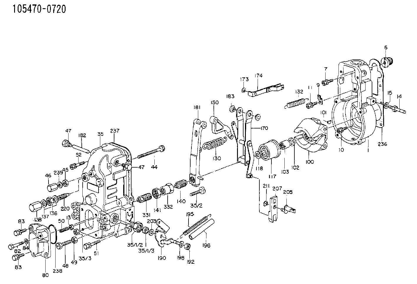
| 1. | [1] | 154000-7800 | GOVERNOR HOUSING |
| 4. | [1] | 154007-2100 | CAPSULE |
| 6. | [1] | 154007-0200 | ADAPTOR |
| 7. | [1] | 020018-1840 | BLEEDER SCREW M8P1.25L18 |
| 9. | [1] | 154350-1800 | PLATE |
| 10. | [5] | 029010-6810 | BLEEDER SCREW |
| 11. | [1] | 020106-1640 | BLEEDER SCREW M6P1.0L14 |
| 13. | [1] | 029240-6010 | UNION NUT M6P1.0H5* |
| 14. | [1] | 154352-3020 | BLEEDER SCREW |
| 15. | [1] | 014110-8440 | LOCKING WASHER |
| 35. | [1] | 154597-0820 | GOVERNOR COVER |
| 35/1. | [1] | 154510-2120 | GOVERNOR COVER |
| 35/1/2. | [1] | 154321-1800 | BUSHING |
| 35/1/2. | [1] | 154321-1800 | BUSHING |
| 35/1/3. | [1] | 029621-0080 | PACKING RING |
| 35/1/3. | [1] | 029621-0080 | PACKING RING |
| 35/2. | [1] | 154031-3200 | FLAT-HEAD SCREW |
| 35/3. | [1] | 154011-1600 | UNION NUT |
| 44. | [1] | 154034-0600 | FLAT-HEAD SCREW |
| 45. | [1] | 029200-8500 | UNION NUT |
| 46. | [1] | 154035-1700 | CAP NUT |
| 47. | [2] | 154036-0300 | CAPSULE |
| 47. | [2] | 154036-0300 | CAPSULE |
| 48. | [1] | 154010-4400 | BLEEDER SCREW |
| 49. | [1] | 029240-8000 | UNION NUT |
| 50. | [1] | 155615-1000 | FLAT-HEAD SCREW |
| 51. | [4] | 020106-3840 | BLEEDER SCREW |
| 52. | [2] | 020106-5040 | BLEEDER SCREW |
| 65. | [1] | 153043-4520 | STOPPING DEVICE |
| 80. | [1] | 154060-0020 | COVER |
| 82. | [1] | 029020-6220 | BLEEDER SCREW |
| 83. | [3] | 020006-1640 | BLEEDER SCREW M6P1L16 4T |
| 83. | [3] | 020006-1640 | BLEEDER SCREW M6P1L16 4T |
| 84. | [1] | 014110-6440 | LOCKING WASHER |
| 100. | [1] | 154100-4020 | FLYWEIGHT ASSEMBLY |
| 101. | [1] | 025803-1610 | WOODRUFF KEY |
| 102. | [1] | 029321-2020 | LOCKING WASHER |
| 103. | [1] | 029231-2030 | UNION NUT |
| 117. | [1] | 154123-1420 | SLIDING PIECE |
| 118/1. | [0] | 029311-0010 | SHIM D14&10.1T0.2 |
| 118/1. | [0] | 029311-0180 | SHIM D14&10.1T0.3 |
| 118/1. | [0] | 029311-0190 | SHIM D14&10.1T0.40 |
| 118/1. | [0] | 029311-0210 | SHIM D14&10.1T1 |
| 118/1. | [0] | 139410-0000 | SHIM D14.0&10.1T0.5 |
| 118/1. | [0] | 139410-0100 | SHIM D14.0&10.1T1.5 |
| 118/1. | [0] | 139410-3000 | SHIM D14&10.1T2.0 |
| 118/1. | [0] | 139410-3100 | SHIM D14&10.1T3.0 |
| 118/1. | [0] | 139410-3200 | SHIM D14&10.1T4.0 |
| 130. | [1] | 154150-2400 | GOVERNOR SPRING |
| 132. | [1] | 154154-1300 | COILED SPRING |
| 136. | [1] | 029201-2140 | UNION NUT |
| 137. | [2] | 139512-0000 | GASKET D17.2&12.2T1.0 |
| 138. | [1] | 154159-1200 | CAP NUT |
| 140. | [1] | 154176-2720 | HEADLESS SCREW |
| 141. | [1] | 029201-6010 | UNION NUT |
| 150. | [1] | 154200-2300 | CONTROL LEVER |
| 170. | [1] | 154211-0420 | FORK LEVER |
| 173. | [1] | 016010-0540 | LOCKING WASHER |
| 174. | [1] | 154230-3920 | STRAP |
| 181. | [1] | 154236-1120 | TENSIONING LEVER |
| 182. | [1] | 154237-0400 | BEARING PIN |
| 183. | [2] | 154237-0600 | BUSHING |
| 190. | [1] | 154305-6120 | CONTROL LEVER |
| 192. | [1] | 013020-8040 | UNION NUT M8P1.25H7 |
| 195. | [2] | 154332-1800 | COILED SPRING |
| 196. | [2] | 154156-0600 | TUBE |
| 198. | [1] | 014110-8440 | LOCKING WASHER |
| 203/1. | [0] | 029311-0220 | SHIM D18&10.3T0.2 |
| 203/1. | [0] | 029311-0230 | SHIM D18&10.3T0.5 |
| 203/1. | [0] | 029311-0430 | SHIM D18&10.3T0.30 |
| 203/1. | [0] | 029311-0440 | SHIM D18&10.3T0.40 |
| 203/1. | [0] | 029311-0450 | SHIM D18&10.3T0.25 |
| 203/1. | [0] | 029311-0460 | SHIM D18&10.3T0.35 |
| 203/1. | [0] | 139410-3300 | SHIM D18&10.3T0.6 |
| 203/1. | [0] | 139410-3400 | SHIM D18&10.3T0.8 |
| 203/1. | [0] | 139410-3500 | SHIM D18&10.3T0.9 |
| 205. | [1] | 154324-1200 | LEVER SHAFT |
| 207. | [1] | 154326-0300 | CONTROL LEVER |
| 211. | [1] | 016010-0810 | LOCKING WASHER |
| 220. | [1] | 154050-1220 | HEADLESS SCREW |
| 236. | [1] | 154390-0000 | GASKET |
| 237. | [1] | 154390-0300 | GASKET |
| 238. | [1] | 029635-2020 | O-RING |
| 239. | [1] | 026508-1240 | GASKET D11.9&8.2T1 |
Cross reference number
Zexel num
Bosch num
Firm num
Name
Information:
Removing Connecting Rod and Piston
Removing Piston PinInspection
Inspect the removed parts. If any parts are found defective, replace or repair them.
Inspection of Piston and Connecting Rod1. Inspection of piston ring gapsPut each piston ring into the cylinder bore and push the ring with piston to position the ring on square with the cylinder wall. Measure the ring gap with a feeler gauge. If the measurement exceeds service limit, replace that piston ring.
Measuring Ring Gap CAUTION* When only the replacement of rings is to be made, without reboring (honing) of the cylinder, position the ring to be measured at the least worn place of cylinder skirt.* When replacing rings, install the new rings having the same size as the piston.* Piston rings available for servicing are sized into three classes: STD, 0.25 OS, and 0.50 OS.2. Inspection of ring groove in pistonMeasure the side clearance for each piston ring set in the ring groove in the piston. If the service limit is exceeded, replace the ring with new one. If the clearance still exceeds the service limit, replace the piston with new one.
Measuring Ring Side Clearance
Note: No. 1 ring is of the semi-key stone typeInstallation
When reassembling the piston and connecting rod and installing the piston-and-rod assemblies in the cylinder block, pay attention to the following:(1) Reassembling the piston and connecting rodUsing the Piston Pin Setting Tool, press the piston pin in to the set position.
Installation of Piston and Connecting Rod
Pressing in Piston Pin(2) Installation of piston rings
Installation of Piston Rings and Connecting Rod Cap(3) Set the piston ring gaps to the proper positions as shown in the figure at right. Coat the rings and cylinder wall with oil.
Proper Arrangement of Ring Gaps(4) Using a piston-ring compressor to compress the rings into the grooves, push the piston-and-rod assembly down into the cylinder. Be sure not to break the rings by excessively knocking the head of piston. Note that the front marks on the piston and connecting rod are toward the engine front.(5) Coat the bearing surface of the connecting rod caps with engine oil. Fit each cap to the connecting rod using match marks put before removal as a guide. In the case of a new rod which does not such a match mark, position the notches (provided for preventing the bearing from rotating) on the same side.
Fitting Cap to Connecting RodCRANKSHAFT
Construction
Crankshaft Component Parts(1) Key(2) Crankshaft(3) Crankshaft gear(4) Crankshaft pulley(5) Nut(6) Washer(7) Spring washer(8) Flywheel(9) Ring gear(10) Rear oil seal(11) Rear oil seal case(12) Gasket(13) Flywheel boltRemoval
(1) Loosen the flywheel bolts and remove the flywheel.(2) Loosen the crankshaft pulley nut and remove the pulley.(3) Remove the rear oil seal case assembly.(4) Remove the bearing caps. Keep each set of bearings removed together with its bearing cap.(5) Take out the crankshaft.
Removing Main Bearing CapInspection
Inspect the removed parts. If any parts are found defective, repair or replace them.
Inspection of Crankshaft and Flywheel1. Checking the crankshaft for wearTo check the crankpins and main journals for tapering wear and out-of-round wear, diameter of each crankpin