Information governor
BOSCH
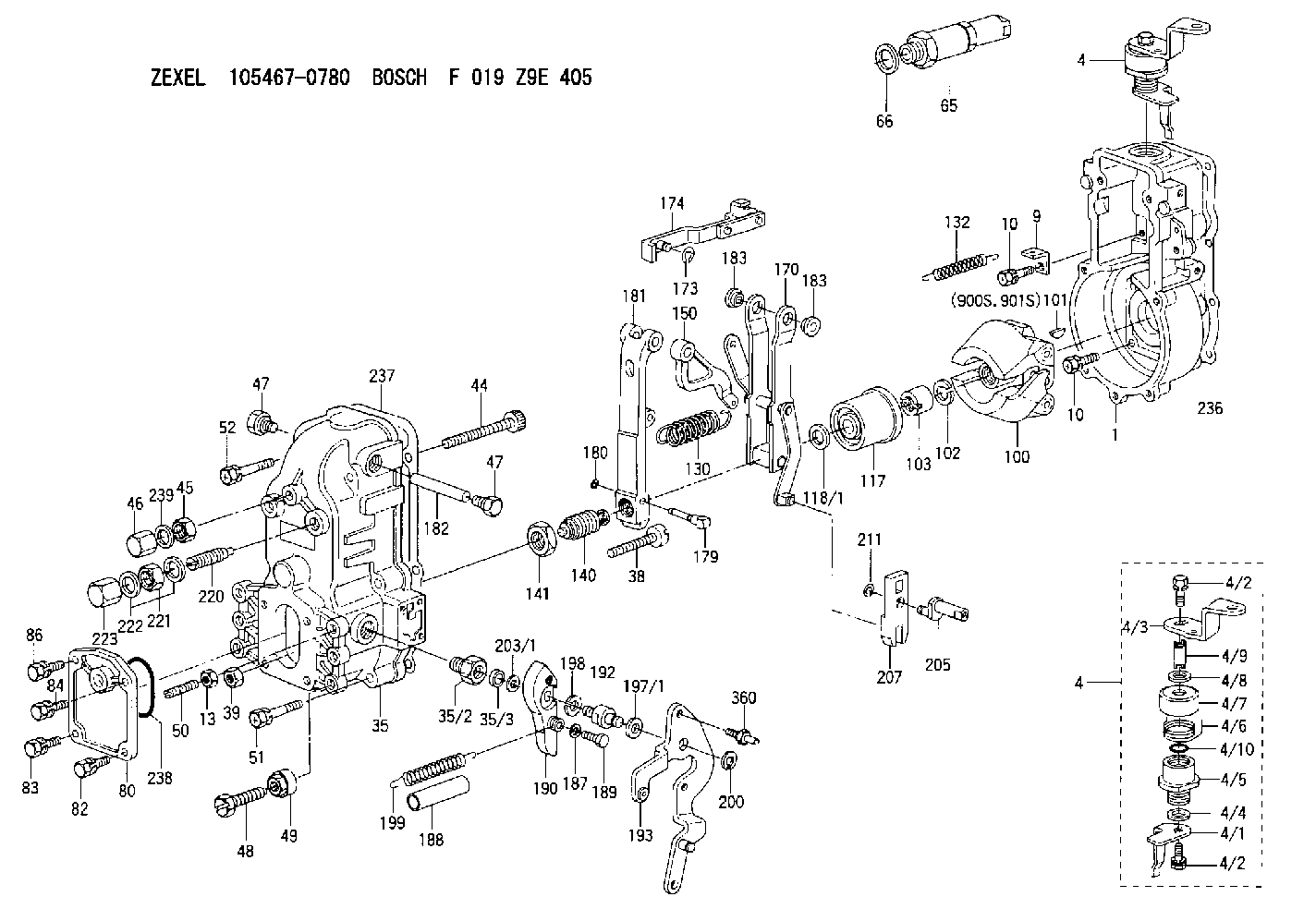
F 019 Z9E 405
f019z9e405
ZEXEL
105467-0780
1054670780
ISUZU
1157702290
1157702290
Rating:
Scheme ###:
| 1. | [1] | 154000-4700 | GOVERNOR HOUSING |
| 4. | [1] | 154364-0420 | CONTROL LEVER |
| 4. | [1] | 154364-0420 | CONTROL LEVER |
| 4/1. | [1] | 154304-6200 | CONTROL LEVER |
| 4/2. | [2] | 154352-2000 | BLEEDER SCREW |
| 4/2. | [2] | 154352-2000 | BLEEDER SCREW |
| 4/3. | [1] | 154364-0400 | CONTROL LEVER |
| 4/4. | [1] | 029311-0230 | SHIM D18&10.3T0.5 |
| 4/5. | [1] | 154321-1500 | BUSHING |
| 4/6. | [1] | 154327-2901 | COILED SPRING |
| 4/7. | [1] | 154322-0100 | CAP |
| 4/8. | [1] | 029311-0220 | SHIM D18&10.3T0.2 |
| 4/9. | [1] | 154324-2700 | LEVER SHAFT |
| 4/10. | [1] | 029631-0030 | O-RING &9.8W2.3 |
| 9. | [1] | 154350-6000 | PLATE |
| 10. | [8] | 020106-2040 | BLEEDER SCREW M6P1L20 |
| 10. | [8] | 020106-2040 | BLEEDER SCREW M6P1L20 |
| 13. | [1] | 029240-6010 | UNION NUT M6P1.0H5* |
| 35. | [1] | 154510-5920 | GOVERNOR COVER |
| 35/2. | [1] | 154321-1800 | BUSHING |
| 35/3. | [1] | 029621-0080 | PACKING RING |
| 38. | [1] | 154031-3500 | FLAT-HEAD SCREW |
| 39. | [1] | 154011-1600 | UNION NUT |
| 44. | [1] | 154034-0600 | FLAT-HEAD SCREW |
| 45. | [1] | 029200-8500 | UNION NUT |
| 46. | [1] | 154035-1700 | CAP NUT |
| 47. | [2] | 154036-0300 | CAPSULE |
| 47. | [2] | 154036-0300 | CAPSULE |
| 48. | [1] | 154010-5500 | BLEEDER SCREW M10P1.25L42 |
| 49. | [1] | 154011-2100 | UNION NUT |
| 50. | [1] | 155615-1100 | FLAT-HEAD SCREW M6P1.0L37 |
| 51. | [4] | 020106-3840 | BLEEDER SCREW |
| 52. | [2] | 020106-5040 | BLEEDER SCREW |
| 65. | [1] | 153043-4120 | STOPPING DEVICE |
| 66. | [1] | 026524-3040 | GASKET |
| 80. | [1] | 154060-4900 | COVER |
| 82. | [1] | 029020-6210 | BLEEDER SCREW |
| 83. | [1] | 020006-1640 | BLEEDER SCREW M6P1L16 4T |
| 84. | [1] | 029020-6210 | BLEEDER SCREW |
| 86. | [1] | 020006-1640 | BLEEDER SCREW M6P1L16 4T |
| 100. | [1] | 154100-9620 | FLYWEIGHT ASSEMBLY |
| 101. | [1] | 025803-1310 | WOODRUFF KEY |
| 102. | [1] | 029321-2020 | LOCKING WASHER |
| 103. | [1] | 029231-2030 | UNION NUT |
| 117. | [1] | 154123-0420 | SLIDING PIECE |
| 118/1. | [0] | 029311-0010 | SHIM D14&10.1T0.2 |
| 118/1. | [0] | 029311-0180 | SHIM D14&10.1T0.3 |
| 118/1. | [0] | 029311-0190 | SHIM D14&10.1T0.40 |
| 118/1. | [0] | 029311-0210 | SHIM D14&10.1T1 |
| 118/1. | [0] | 139410-0000 | SHIM D14.0&10.1T0.5 |
| 118/1. | [0] | 139410-0100 | SHIM D14.0&10.1T1.5 |
| 118/1. | [0] | 139410-3000 | SHIM D14&10.1T2.0 |
| 118/1. | [0] | 139410-3100 | SHIM D14&10.1T3.0 |
| 118/1. | [0] | 139410-3200 | SHIM D14&10.1T4.0 |
| 130. | [1] | 154150-2200 | GOVERNOR SPRING |
| 132. | [1] | 154154-1200 | COILED SPRING |
| 140. | [1] | 154175-1520 | HEADLESS SCREW |
| 141. | [1] | 029201-6010 | UNION NUT |
| 150. | [1] | 154200-2300 | CONTROL LEVER |
| 170. | [1] | 154211-7720 | GUIDE LEVER |
| 173. | [1] | 016010-0540 | LOCKING WASHER |
| 174. | [1] | 154230-4920 | STRAP |
| 179. | [1] | 154238-0301 | BEARING PIN |
| 180. | [1] | 016010-0540 | LOCKING WASHER |
| 181. | [1] | 154236-5300 | TENSIONING LEVER |
| 182. | [1] | 154237-0400 | BEARING PIN |
| 183. | [2] | 154237-0600 | BUSHING |
| 183. | [2] | 154237-0600 | BUSHING |
| 187. | [1] | 014110-6440 | LOCKING WASHER |
| 188. | [1] | 154156-1500 | TUBE |
| 189. | [1] | 154357-6320 | BLEEDER SCREW |
| 190. | [1] | 154360-2800 | CONTROL LEVER |
| 192. | [1] | 154357-6401 | BLEEDER SCREW |
| 193. | [1] | 154363-7420 | CONTROL LEVER |
| 197/1. | [0] | 029310-8610 | SHIM D10.5&8.5T0.1 |
| 197/1. | [0] | 029310-8620 | SHIM D10.5&8.5T0.15 |
| 197/1. | [0] | 029310-8630 | SHIM D10.5&8.5T0.2 |
| 197/1. | [0] | 029310-8650 | SHIM D10.5&8.5T0.5 |
| 198. | [1] | 014110-8440 | LOCKING WASHER |
| 199. | [1] | 154317-0900 | COILED SPRING |
| 200. | [1] | 016010-0740 | LOCKING WASHER |
| 203/1. | [0] | 029311-0640 | SHIM D26.0&10.2T0.95 |
| 203/1. | [0] | 029311-0650 | SHIM D26.0&10.2T0.20 |
| 203/1. | [0] | 029311-0660 | SHIM D26.0&10.2T0.25 |
| 203/1. | [0] | 029311-0670 | SHIM D26.0&10.2T0.30 |
| 203/1. | [0] | 029311-0680 | SHIM D26.0&10.2T0.35 |
| 203/1. | [0] | 029311-0690 | SHIM D26.0&10.2T0.40 |
| 203/1. | [0] | 029311-0700 | SHIM D26.0&10.2T0.50 |
| 203/1. | [0] | 139410-1400 | SHIM D26&10.2T0.7 |
| 203/1. | [0] | 139410-1500 | SHIM D26&10.2T0.9 |
| 203/1. | [0] | 139410-1600 | SHIM D26&10.2T0.8 |
| 203/1. | [0] | 139410-2700 | SHIM D26&10.2T0.6 |
| 205. | [1] | 154324-4500 | LEVER SHAFT |
| 207. | [1] | 154326-0300 | CONTROL LEVER |
| 211. | [1] | 016010-0840 | LOCKING WASHER |
| 220. | [1] | 154050-6220 | HEADLESS SCREW |
| 221. | [1] | 029201-2130 | UNION NUT M12P1.0H6 |
| 222. | [2] | 139512-0000 | GASKET D17.2&12.2T1.0 |
| 223. | [1] | 154159-1200 | CAP NUT |
| 236. | [1] | 154371-5600 | GASKET |
| 237. | [1] | 154390-0300 | GASKET |
| 238. | [1] | 029635-2020 | O-RING |
| 239. | [1] | 026508-1240 | GASKET D11.9&8.2T1 |
| 360. | [1] | 154357-6900 | BEARING PIN |
| 900S. | [1] | 025803-1310 | WOODRUFF KEY |
| 901S. | [1] | 025803-1610 | WOODRUFF KEY |
Include in #1:
106693-1490
as GOVERNOR
Cross reference number
Zexel num
Bosch num
Firm num
Name
105467-0780
F 019 Z9E 405
1157702290 ISUZU
GOVERNOR
* K
* K
Information:
When fuel has stopped flowing out, turn the crankshaft slightly in the reverse direction such that fuel flows out. Then, slowly turn the crankshaft clockwise again to more accurately verify the point at which fuel stops flowing out.
End of fuel flow(c) If the IT mark on the crankshaft pulley and the mark on the gear case are aligned when fuel stops flowing out the injection timing is normal.
Timing marks(3) Adjustment
(a) If the injection timing is out of specification, make adjustments by increasing or decreasing the thickness of the injection pump's mounting shim. A change of 0.1 mm in the shim thickness yields a change of approximately 1° in the injection timing.
Injection timing adjusting shim(b) Increasing the shim thickness retards the injection timing, and decreasing the shim thickness advances it. Shims come in 9 different thicknesses from 0.2 mm (0.008 in.) to 1.0 mm (0.039 in.) at intervals of 0.1 mm (0.004 in.). The thickness is not indicated on the shim, so any shim should be measured with a vernier caliper before being used.
Before using any shim, apply sealant to both sides to prevent oil leakage.
(c) After making adjustments, check the injection timing is correct.(d) Close the cock on the fuel filter, then fit the delivery valve spring and injection pipe in their original positions.
Adjusting injection timingAdjusting Idle Speed
(1) Preparation for Adjustment
(a) Warm up the engine unit the coolant reaches a temperature of 60°C (140°F) or higher.(b) Make sure the valve clearances, injection timing, and injectors are normal.(2) Adjusting Low-Idle Speed
Loosen the locknut on the idling set bolt, turn the bolt to achieve the specified low-idle speed (1000 25min-1), then tighten the lock nut to hold the bolt in that position.(3) Adjusting No-Load Maximum Speed
Loosen the lock nut on the high-speed set bolt, turn the bolt to achieve the specified no-load maximum speed (2600 +30-10 min-1), then tighten the lock nut to hold the bolt in that position.
Adjusting idle speedAdjusting Fan Belt Tension
(1) Press the fan belt with the specified force mid-way between the alternator pulley and crankshaft pulley, and observe the extent of deflection.Unit: mm (in.) (2) If the extent of deflection is out of specification, loosen the adjusting bolt and adjust the fan belt tension by moving the alternator. Retighten the adjusting bolt securely.
Adjusting fan belt tensionRunning in the Engine
After an overhaul, the engine should be tested and inspected on a dynamometer. This operation serves to run in the engine's major moving parts.Starting the Engine
(1) Before starting the engine, check the coolant, engine oil and fuel levels and bleed all air out of the fuel and cooling systems.(2) Without supplying fuel to the engine, crank the engine for about 10 seconds to permit oil to circulate through it.(3) Move the speed control lever slightly in the fuel-increase direction. (Do not move the lever to the full-injection position.) Then, turn the starter switch to the START position to start the engine.(4) Once the engine has started, set it to the low-idle speed using the speed control lever.Inspection after
Have questions with 105467-0780?
Group cross 105467-0780 ZEXEL
Isuzu
Isuzu
105467-0780
F 019 Z9E 405
1157702290
GOVERNOR