Information governor
BOSCH
F 019 Z9E 799
f019z9e799
ZEXEL
105467-0612
1054670612

Rating:
Scheme ###:
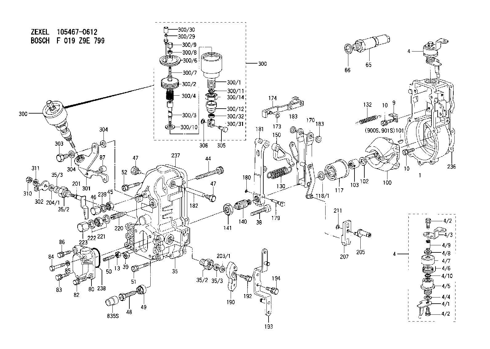
| 1. | [1] | 154000-4700 | GOVERNOR HOUSING |
| 4. | [1] | 154364-0420 | CONTROL LEVER |
| 4. | [1] | 154364-0420 | CONTROL LEVER |
| 4/1. | [1] | 154304-6200 | CONTROL LEVER |
| 4/2. | [2] | 154352-2000 | BLEEDER SCREW |
| 4/2. | [2] | 154352-2000 | BLEEDER SCREW |
| 4/3. | [1] | 154364-0400 | CONTROL LEVER |
| 4/4. | [1] | 029311-0230 | SHIM D18&10.3T0.5 |
| 4/5. | [1] | 154321-1500 | BUSHING |
| 4/6. | [1] | 154327-2901 | COILED SPRING |
| 4/7. | [1] | 154322-0100 | CAP |
| 4/8. | [1] | 029311-0220 | SHIM D18&10.3T0.2 |
| 4/9. | [1] | 154324-2700 | LEVER SHAFT |
| 4/10. | [1] | 029631-0030 | O-RING &9.8W2.3 |
| 9. | [1] | 154350-6000 | PLATE |
| 10. | [8] | 020106-2040 | BLEEDER SCREW M6P1L20 |
| 10. | [8] | 020106-2040 | BLEEDER SCREW M6P1L20 |
| 13. | [1] | 029240-6010 | UNION NUT M6P1.0H5* |
| 35. | [1] | 154510-8120 | GOVERNOR COVER |
| 35/2. | [2] | 154321-1800 | BUSHING |
| 35/2. | [2] | 154321-1800 | BUSHING |
| 35/3. | [2] | 029621-0080 | PACKING RING |
| 35/3. | [2] | 029621-0080 | PACKING RING |
| 38. | [1] | 154031-3500 | FLAT-HEAD SCREW |
| 39. | [1] | 154011-1600 | UNION NUT |
| 44. | [1] | 154034-2300 | FLAT-HEAD SCREW |
| 45. | [1] | 154011-2500 | UNION NUT |
| 46. | [1] | 154035-2100 | CAP NUT |
| 47. | [2] | 154036-0300 | CAPSULE |
| 47. | [2] | 154036-0300 | CAPSULE |
| 48. | [1] | 154010-7700 | BLEEDER SCREW M10P1.25L51 |
| 48B. | [1] | 154010-7100 | BLEEDER SCREW M10P1.25L47 |
| 49. | [1] | 154011-2200 | UNION NUT |
| 50. | [1] | 155615-1100 | FLAT-HEAD SCREW M6P1.0L37 |
| 51. | [4] | 020106-3840 | BLEEDER SCREW |
| 52. | [2] | 020106-5040 | BLEEDER SCREW |
| 65. | [1] | 153043-5220 | STOPPING DEVICE |
| 66. | [1] | 026524-3040 | GASKET |
| 80. | [1] | 154060-7900 | COVER |
| 82. | [1] | 029020-6210 | BLEEDER SCREW |
| 83. | [1] | 020006-1640 | BLEEDER SCREW M6P1L16 4T |
| 84. | [1] | 029020-6250 | BLEEDER SCREW |
| 85. | [1] | 014110-6440 | LOCKING WASHER |
| 86. | [1] | 020006-4540 | BLEEDER SCREW M6P1L45 |
| 87. | [1] | 154356-2700 | SPACER BUSHING |
| 100. | [1] | 154100-9620 | FLYWEIGHT ASSEMBLY |
| 101. | [1] | 025803-1310 | WOODRUFF KEY |
| 102. | [1] | 029321-2020 | LOCKING WASHER |
| 103. | [1] | 029231-2030 | UNION NUT |
| 117. | [1] | 154123-0420 | SLIDING PIECE |
| 118/1. | [0] | 029311-0010 | SHIM D14&10.1T0.2 |
| 118/1. | [0] | 029311-0180 | SHIM D14&10.1T0.3 |
| 118/1. | [0] | 029311-0190 | SHIM D14&10.1T0.40 |
| 118/1. | [0] | 029311-0210 | SHIM D14&10.1T1 |
| 118/1. | [0] | 139410-0000 | SHIM D14.0&10.1T0.5 |
| 118/1. | [0] | 139410-0100 | SHIM D14.0&10.1T1.5 |
| 118/1. | [0] | 139410-3000 | SHIM D14&10.1T2.0 |
| 118/1. | [0] | 139410-3100 | SHIM D14&10.1T3.0 |
| 118/1. | [0] | 139410-3200 | SHIM D14&10.1T4.0 |
| 130. | [1] | 154150-2200 | GOVERNOR SPRING |
| 132. | [1] | 154154-1200 | COILED SPRING |
| 140. | [1] | 154175-1520 | HEADLESS SCREW |
| 141. | [1] | 029201-6010 | UNION NUT |
| 150. | [1] | 154200-2300 | CONTROL LEVER |
| 170. | [1] | 154216-6020 | FORK LEVER |
| 173. | [1] | 016010-0540 | LOCKING WASHER |
| 174. | [1] | 154230-4920 | STRAP |
| 179. | [1] | 154238-0301 | BEARING PIN |
| 180. | [1] | 016010-0540 | LOCKING WASHER |
| 181. | [1] | 154236-5300 | TENSIONING LEVER |
| 182. | [1] | 154237-0400 | BEARING PIN |
| 183. | [2] | 154237-0600 | BUSHING |
| 183. | [2] | 154237-0600 | BUSHING |
| 190. | [1] | 154360-8100 | CONTROL LEVER |
| 192. | [1] | 020006-1670 | BLEEDER SCREW M6P1L16 7T |
| 193. | [1] | 154360-7520 | CONTROL LEVER |
| 194. | [2] | 020006-1240 | BLEEDER SCREW M6P1L12 4T |
| 201. | [1] | 154324-3220 | LEVER SHAFT |
| 203/1. | [0] | 029311-0640 | SHIM D26.0&10.2T0.95 |
| 203/1. | [0] | 029311-0650 | SHIM D26.0&10.2T0.20 |
| 203/1. | [0] | 029311-0660 | SHIM D26.0&10.2T0.25 |
| 203/1. | [0] | 029311-0670 | SHIM D26.0&10.2T0.30 |
| 203/1. | [0] | 029311-0680 | SHIM D26.0&10.2T0.35 |
| 203/1. | [0] | 029311-0690 | SHIM D26.0&10.2T0.40 |
| 203/1. | [0] | 029311-0700 | SHIM D26.0&10.2T0.50 |
| 203/1. | [0] | 139410-1400 | SHIM D26&10.2T0.7 |
| 203/1. | [0] | 139410-1500 | SHIM D26&10.2T0.9 |
| 203/1. | [0] | 139410-1600 | SHIM D26&10.2T0.8 |
| 203/1. | [0] | 139410-2700 | SHIM D26&10.2T0.6 |
| 204/1. | [0] | 029311-0520 | SHIM D20.8&10.3T0.2 |
| 204/1. | [0] | 029311-0530 | SHIM D20.8&10.3T0.25 |
| 204/1. | [0] | 029311-0540 | SHIM D20.8&10.3T0.3 |
| 204/1. | [0] | 029311-0550 | SHIM D20.8&10.3T0.35 |
| 204/1. | [0] | 029311-0560 | SHIM D20.8&10.3T0.4 |
| 204/1. | [0] | 029311-0570 | SHIM D20.8&10.3T0.5 |
| 205. | [1] | 154324-3100 | LEVER SHAFT |
| 207. | [1] | 154326-0300 | CONTROL LEVER |
| 211. | [1] | 016010-0840 | LOCKING WASHER |
| 220. | [1] | 154050-1220 | HEADLESS SCREW |
| 221. | [1] | 029201-2140 | UNION NUT |
| 222. | [2] | 139512-0000 | GASKET D17.2&12.2T1.0 |
| 223. | [1] | 154159-1200 | CAP NUT |
| 236. | [1] | 154371-5600 | GASKET |
| 237. | [1] | 154390-0300 | GASKET |
| 238. | [1] | 029635-2020 | O-RING |
| 239. | [1] | 026508-1240 | GASKET D11.9&8.2T1 |
| 300. | [1] | 155423-6920 | ANEROID CAPSULE |
| 300. | [1] | 155423-6920 | ANEROID CAPSULE |
| 300/1. | [1] | 155423-3720 | DIAPHRAGM HOUSING |
| 300/2. | [1] | 155403-3021 | BELLOWS |
| 300/3. | [1] | 155423-5920 | STOP PIN |
| 300/4. | [1] | 155423-4400 | COILED SPRING |
| 300/6. | [1] | 155423-2000 | COVER |
| 300/7. | [1] | 155423-1500 | SCREW PLUG |
| 300/8. | [1] | 029240-6010 | UNION NUT M6P1.0H5* |
| 300/9. | [1] | 154035-1600 | CAP NUT |
| 300/10. | [1] | 029311-2060 | SHIM D22&12.5T0.5 |
| 300/11. | [1] | 016020-1220 | LOCKING WASHER |
| 300/12. | [1] | 155403-2200 | COVER |
| 300/14. | [1] | 139222-0000 | UNION NUT |
| 300/29. | [1] | 139805-0000 | JOINT CONNECTION |
| 300/30. | [1] | 155424-0300 | CAP |
| 300/31. | [1] | 155423-6000 | CLEVIS |
| 300/32. | [1] | 029200-5130 | UNION NUT |
| 301. | [1] | 154356-2420 | BRACKET |
| 302. | [1] | 154363-1300 | CONTROL LEVER |
| 302B. | [1] | 154363-1400 | CONTROL LEVER |
| 303. | [1] | 139012-0000 | BLEEDER SCREW |
| 304. | [2] | 139512-0000 | GASKET D17.2&12.2T1.0 |
| 304. | [2] | 139512-0000 | GASKET D17.2&12.2T1.0 |
| 305. | [1] | 154222-7800 | BEARING PIN |
| 306. | [1] | 016010-0540 | LOCKING WASHER |
| 310. | [1] | 013020-6040 | UNION NUT M6P1H5 |
| 311. | [1] | 014110-6440 | LOCKING WASHER |
| 835S. | [2] | 154062-1700 | CAP D20L32 |
| 900S. | [1] | 025803-1310 | WOODRUFF KEY |
| 901S. | [1] | 025803-1610 | WOODRUFF KEY |
Cross reference number
Zexel num
Bosch num
Firm num
Name
Information:
In this manual, specifications, service standards, adjustment procedures, disassembly procedures, inspection procedures, and reassembly procedures for the engine are shown in groups. The contents of each group are listed in the index and at the beginning of that group.For instructions on operation and periodic inspection, refer to the operation manual. For instructions on ordering replacement parts, refer to the parts catalog. For information on the engine's structure and function, refer to relevant training material.1. Items Shown in This Manual(1) Parts mentioned in the text and shown in the exploded views are numbered in their disassembly sequences.(2) Inspections to be performed during disassembly are shown in in the exploded views.(3) Service standards for inspection and repair operations are indicated at relevant places in the text and in a table in Group 2.(4) The sequences in which parts should be reassembled during reassembly operations are shown under reassembly drawings in this manner: .(5) The symbols and headings shown below are used in this manual to highlight particularly important and safety-critical instructions.
Indicates a condition that will cause death or serious injury if incorrect action is taken.
Indicates a condition that may cause death or serious injury if incorrect action is taken.
Indicates a condition that will cause engine damage or slight or moderate injury if incorrect action is taken.
Indicates a supplementary explanation or other important point.(6) With regard to tightening torques, points to which engine oil must be applied are labeled "Wet". Where there is no such indication, parts should be tightened in a dry condition.2. TerminologyTerms used in this manual are defined as follows:(1) Front and RearThe term "front" refers to the fan side of the engine, and the term "rear" applies to the flywheel side.(2) Left and RightThe terms "left" and "right" apply to the sides of the engine as seen from the flywheel.(3) Service Standards* Standard ValueThis term indicates a designed nominal dimension, the designed dimension of a single part, the standard clearance between two parts after assembly, or a standard performance value for an assembly.* LimitThis term indicates a value beyond which a part is no longer useable in terms of performance and strength and must be repaired or replaced.