Information governor
BOSCH
F 019 Z1E 627
f019z1e627
ZEXEL
105462-7140
1054627140
NISSAN-DIESEL
19200Z5508
19200z5508
Rating:
Scheme ###:
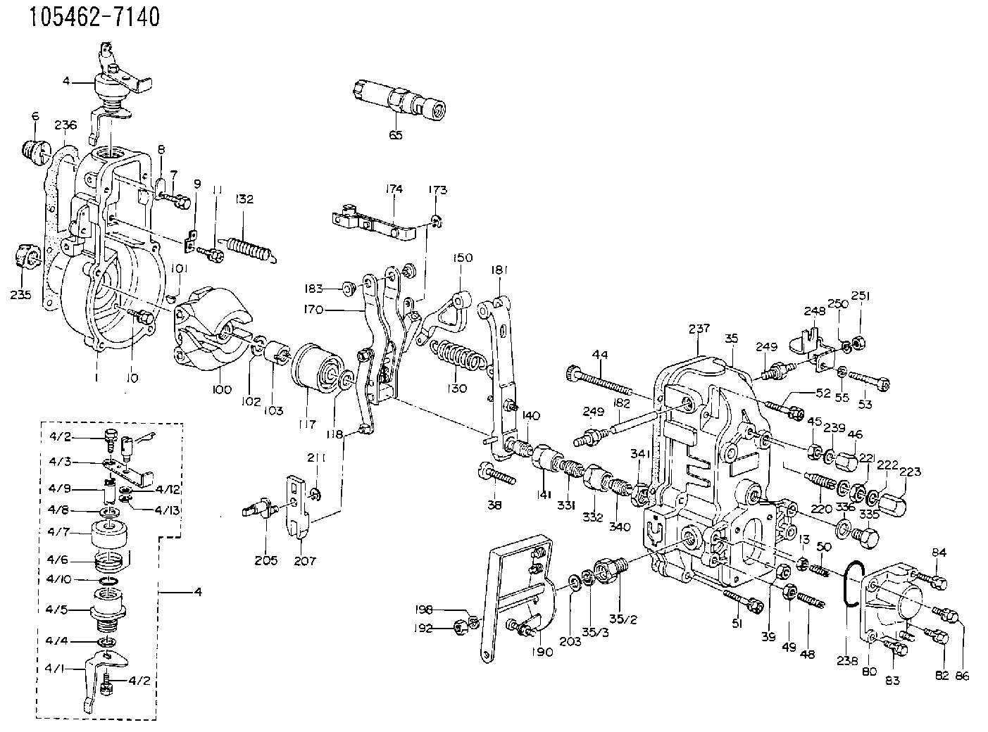
| 1. | [1] | 154000-8200 | GOVERNOR HOUSING |
| 4. | [1] | 154304-0620 | CONTROL LEVER |
| 4. | [1] | 154304-0620 | CONTROL LEVER |
| 4/1. | [1] | 154304-3600 | CONTROL LEVER |
| 4/2. | [2] | 154352-2000 | BLEEDER SCREW |
| 4/2. | [2] | 154352-2000 | BLEEDER SCREW |
| 4/3. | [1] | 154304-0600 | CONTROL LEVER |
| 4/4. | [1] | 029311-0230 | SHIM D18&10.3T0.5 |
| 4/5. | [1] | 154321-1500 | BUSHING |
| 4/6. | [1] | 154327-2901 | COILED SPRING |
| 4/7. | [1] | 154322-0100 | CAP |
| 4/8. | [1] | 029311-0220 | SHIM D18&10.3T0.2 |
| 4/9. | [1] | 154324-2700 | LEVER SHAFT |
| 4/10. | [1] | 029631-0030 | O-RING &9.8W2.3 |
| 4/12. | [0] | 029310-8030 | SHIM D13.5&8T0.1 |
| 4/12. | [0] | 029310-8040 | SHIM D13.5&8T0.2 |
| 4/12. | [0] | 029310-8050 | SHIM D13.5&8T0.5 |
| 4/13. | [1] | 016010-0740 | LOCKING WASHER |
| 4/14. | [1] | 029451-8020 | SAFETY PIN |
| 6. | [1] | 154007-0200 | ADAPTOR |
| 7. | [1] | 020018-2240 | BLEEDER SCREW M8P1.25L22 |
| 8. | [1] | 154353-4400 | PLATE |
| 9. | [1] | 154350-1800 | PLATE |
| 10. | [5] | 029010-6810 | BLEEDER SCREW |
| 11. | [1] | 020106-1640 | BLEEDER SCREW M6P1.0L14 |
| 13. | [1] | 029240-6010 | UNION NUT M6P1.0H5* |
| 35. | [1] | 154510-5120 | GOVERNOR COVER |
| 35/2. | [1] | 154321-1800 | BUSHING |
| 35/3. | [1] | 029621-0080 | PACKING RING |
| 38. | [1] | 154031-3200 | FLAT-HEAD SCREW |
| 39. | [1] | 154011-1600 | UNION NUT |
| 44. | [1] | 154034-0600 | FLAT-HEAD SCREW |
| 45. | [1] | 029200-8500 | UNION NUT |
| 46. | [1] | 154035-1700 | CAP NUT |
| 48. | [1] | 154010-5400 | FLAT-HEAD SCREW |
| 49. | [1] | 029240-8000 | UNION NUT |
| 50. | [1] | 155615-1000 | FLAT-HEAD SCREW |
| 51. | [4] | 020106-3840 | BLEEDER SCREW |
| 52. | [1] | 020106-5040 | BLEEDER SCREW |
| 53. | [1] | 029010-6850 | BLEEDER SCREW |
| 55. | [1] | 014110-6440 | LOCKING WASHER |
| 65. | [1] | 153020-4220 | STOPPING DEVICE |
| 80. | [1] | 154063-0620 | COVER |
| 80/1. | [1] | 154063-0600 | COVER |
| 80/2. | [1] | 139010-0000 | STUD |
| 82. | [1] | 020006-1640 | BLEEDER SCREW M6P1L16 4T |
| 83. | [1] | 029020-6210 | BLEEDER SCREW |
| 84. | [1] | 010006-3840 | BLEEDER SCREW |
| 86. | [1] | 029020-6210 | BLEEDER SCREW |
| 100. | [1] | 154100-5020 | FLYWEIGHT ASSEMBLY |
| 101. | [1] | 025803-1610 | WOODRUFF KEY |
| 102. | [1] | 029321-2020 | LOCKING WASHER |
| 103. | [1] | 029231-2030 | UNION NUT |
| 117. | [1] | 154123-1420 | SLIDING PIECE |
| 118/1. | [0] | 029311-0010 | SHIM D14&10.1T0.2 |
| 118/1. | [0] | 029311-0180 | SHIM D14&10.1T0.3 |
| 118/1. | [0] | 029311-0190 | SHIM D14&10.1T0.40 |
| 118/1. | [0] | 029311-0210 | SHIM D14&10.1T1 |
| 118/1. | [0] | 139410-0000 | SHIM D14.0&10.1T0.5 |
| 118/1. | [0] | 139410-0100 | SHIM D14.0&10.1T1.5 |
| 118/1. | [0] | 139410-3000 | SHIM D14&10.1T2.0 |
| 118/1. | [0] | 139410-3100 | SHIM D14&10.1T3.0 |
| 118/1. | [0] | 139410-3200 | SHIM D14&10.1T4.0 |
| 130. | [1] | 154150-2400 | GOVERNOR SPRING |
| 132. | [1] | 154154-1300 | COILED SPRING |
| 140. | [1] | 154176-6320 | HEADLESS SCREW |
| 141. | [1] | 029201-6080 | UNION NUT |
| 150. | [1] | 154200-2300 | CONTROL LEVER |
| 170. | [1] | 154216-0220 | FORK LEVER |
| 173. | [1] | 016010-0540 | LOCKING WASHER |
| 174. | [1] | 154230-4820 | STRAP |
| 181. | [1] | 154236-3620 | TENSIONING LEVER |
| 182. | [1] | 154237-0400 | BEARING PIN |
| 183. | [2] | 154237-0600 | BUSHING |
| 190. | [1] | 154305-6720 | CONTROL LEVER |
| 192. | [1] | 013020-8040 | UNION NUT M8P1.25H7 |
| 198. | [1] | 014110-8440 | LOCKING WASHER |
| 203/1. | [0] | 029311-0640 | SHIM D26.0&10.2T0.95 |
| 203/1. | [0] | 029311-0650 | SHIM D26.0&10.2T0.20 |
| 203/1. | [0] | 029311-0660 | SHIM D26.0&10.2T0.25 |
| 203/1. | [0] | 029311-0670 | SHIM D26.0&10.2T0.30 |
| 203/1. | [0] | 029311-0680 | SHIM D26.0&10.2T0.35 |
| 203/1. | [0] | 029311-0690 | SHIM D26.0&10.2T0.40 |
| 203/1. | [0] | 029311-0700 | SHIM D26.0&10.2T0.50 |
| 203/1. | [0] | 139410-1400 | SHIM D26&10.2T0.7 |
| 203/1. | [0] | 139410-1500 | SHIM D26&10.2T0.9 |
| 203/1. | [0] | 139410-1600 | SHIM D26&10.2T0.8 |
| 203/1. | [0] | 139410-2700 | SHIM D26&10.2T0.6 |
| 205. | [1] | 154324-1200 | LEVER SHAFT |
| 207. | [1] | 154326-0300 | CONTROL LEVER |
| 211. | [1] | 016010-0840 | LOCKING WASHER |
| 220. | [1] | 154050-2320 | HEADLESS SCREW |
| 221. | [1] | 029201-2140 | UNION NUT |
| 222. | [2] | 026512-1540 | GASKET D15.4&12.2T1.50 |
| 223. | [1] | 154159-1200 | CAP NUT |
| 235. | [1] | 155412-5200 | IMPELLER WHEEL |
| 236. | [1] | 154390-0000 | GASKET |
| 237. | [1] | 154390-0300 | GASKET |
| 238. | [1] | 029635-2020 | O-RING |
| 239. | [1] | 026508-1240 | GASKET D11.9&8.2T1 |
| 248. | [1] | 154316-8800 | PLATE |
| 249. | [2] | 154036-1100 | CAPSULE |
| 249. | [2] | 154036-1100 | CAPSULE |
| 250. | [1] | 014110-6440 | LOCKING WASHER |
| 251. | [1] | 013020-6040 | UNION NUT M6P1H5 |
| 331. | [1] | 154185-1320 | HEADLESS SCREW |
| 332. | [1] | 029201-6220 | UNION NUT |
| 335. | [1] | 154352-2600 | CAPSULE |
| 336. | [1] | 029331-6030 | GASKET |
| 340. | [1] | 154172-7820 | HEADLESS SCREW |
| 341. | [1] | 029201-6010 | UNION NUT |
Include in #1:
101691-9080
as GOVERNOR
Cross reference number
Zexel num
Bosch num
Firm num
Name
Information:
Operations that may cause product damage are identified by notice labels in this publication.
Introduction
This Tool Operating Manual contains two filter installation procedures. This first procedure is for installing a primary filter system. This is a coarse filter and will protect the transfer pump from contamination in the oil. The second procedure outlines installing a secondary filter which is designed to protect injection pumps from contaminated oil. Fuel injection pumps used on the 3208 Engine are one example of a fuel injection pump that requires the secondary filter installation.It will be the dealer choice as to which optional filter is installed on the test stand. Determine what type of filtering will be required most often, and install the appropriate type of filtering system. These filters can only be added to the 15 horsepower test stands.Secondary Filter
Nomenclature
Illustration 1. Nomenclature for Secondary Filter Installation. Refer to Chart A for item identification. Fabricated Parts
All the parts required for this installation can be ordered from Caterpillar Parts Distribution, except bracket (1). This must be manufactured by the bench owner, using the dimensions provided below.This bracket can be made from common SAE1018 steel. Weld the two pieces together.
Illustration 2. Filter Mounting Bracket. Refer to Chart B for dimensions. Installation
Assemble the Fuel Filter
1. Install 053-0088 Fitting (17) with 3J-1907 Seal (18) into the inlet port (left side) of the filter base. (This converts a number 6 STOP port to NPT). Install 5P-4455 Fitting (19) into fitting (17).2. Install 2R-6806 Fitting (15) with 3J-1907 Seal (16) into the outlet port (right side) of the filter base.3. Install 6N-4414 Cover (7) onto the filter base using 1P-0436 Gasket (8), 4B-3388/6V-2317 (9), and OS-1616/6V-8490 Bolt (10).4. Install 9S-4182 Plug (5) with 6V-5084 O-ring Seal (6) into the top of the filter base.5. Install the filter base assembly onto filter bracket (1),