Information governor
BOSCH
F 019 Z1E 623
f019z1e623
ZEXEL
105461-0130
1054610130
NISSAN-DIESEL
19200Z5616
19200z5616
Rating:
Scheme ###:
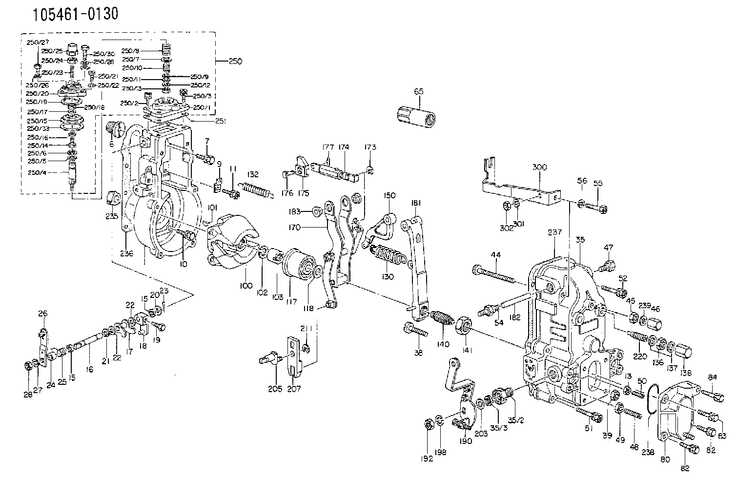
| 1. | [1] | 154000-8020 | GOVERNOR HOUSING |
| 6. | [1] | 154007-0200 | ADAPTOR |
| 7. | [1] | 020018-1640 | BLEEDER SCREW M8P1.25L16 4T |
| 9. | [1] | 154350-1800 | PLATE |
| 10. | [5] | 029010-6810 | BLEEDER SCREW |
| 11. | [1] | 020106-1640 | BLEEDER SCREW M6P1.0L14 |
| 13. | [1] | 029240-6010 | UNION NUT M6P1.0H5* |
| 15. | [2] | 029620-8050 | PACKING RING |
| 15. | [2] | 029620-8050 | PACKING RING |
| 16. | [1] | 155004-3200 | LEVER SHAFT |
| 17. | [1] | 154408-1520 | CONTROL LEVER |
| 18. | [1] | 155003-1920 | CONTROL LEVER |
| 19. | [1] | 155006-0700 | BLEEDER SCREW |
| 20. | [1] | 139308-0900 | PLAIN WASHER D16&8T1 |
| 20B. | [1] | 139308-1000 | PLAIN WASHER D16&8T1.5 |
| 21. | [1] | 016010-0740 | LOCKING WASHER |
| 22. | [0] | 029310-8040 | SHIM D13.5&8T0.2 |
| 22. | [0] | 029310-8040 | SHIM D13.5&8T0.2 |
| 22B. | [0] | 029310-8050 | SHIM D13.5&8T0.5 |
| 23. | [1] | 025520-1210 | SPLIT PIN |
| 24. | [1] | 154206-2000 | BUSHING |
| 25. | [1] | 154327-3600 | COILED SPRING |
| 26. | [1] | 154304-3820 | CONTROL LEVER |
| 27. | [1] | 014110-8440 | LOCKING WASHER |
| 28. | [1] | 013020-8040 | UNION NUT M8P1.25H7 |
| 35. | [1] | 154510-2020 | GOVERNOR COVER |
| 35/2. | [1] | 154321-1800 | BUSHING |
| 35/3. | [1] | 029621-0080 | PACKING RING |
| 38. | [1] | 154031-3200 | FLAT-HEAD SCREW |
| 39. | [1] | 154011-1600 | UNION NUT |
| 44. | [1] | 154034-0600 | FLAT-HEAD SCREW |
| 45. | [1] | 029200-8500 | UNION NUT |
| 46. | [1] | 154035-1700 | CAP NUT |
| 47. | [1] | 154036-0300 | CAPSULE |
| 48. | [1] | 154010-5400 | FLAT-HEAD SCREW |
| 49. | [1] | 029240-8000 | UNION NUT |
| 50. | [1] | 155615-1000 | FLAT-HEAD SCREW |
| 51. | [4] | 020106-3840 | BLEEDER SCREW |
| 52. | [1] | 020106-5040 | BLEEDER SCREW |
| 54. | [1] | 154036-1100 | CAPSULE |
| 55. | [1] | 139106-0900 | BLEEDER SCREW |
| 56. | [1] | 014110-6440 | LOCKING WASHER |
| 65. | [1] | 155404-5700 | CAP |
| 80. | [1] | 154060-0020 | COVER |
| 82. | [2] | 029020-6210 | BLEEDER SCREW |
| 82. | [2] | 029020-6210 | BLEEDER SCREW |
| 83. | [1] | 020006-1640 | BLEEDER SCREW M6P1L16 4T |
| 84. | [1] | 029000-6800 | BLEEDER SCREW |
| 100. | [1] | 154100-5020 | FLYWEIGHT ASSEMBLY |
| 101. | [1] | 025803-1610 | WOODRUFF KEY |
| 102. | [1] | 029321-2020 | LOCKING WASHER |
| 103. | [1] | 029231-2030 | UNION NUT |
| 117. | [1] | 154123-1020 | SLIDING PIECE |
| 118/1. | [0] | 029311-0010 | SHIM D14&10.1T0.2 |
| 118/1. | [0] | 029311-0180 | SHIM D14&10.1T0.3 |
| 118/1. | [0] | 029311-0190 | SHIM D14&10.1T0.40 |
| 118/1. | [0] | 029311-0210 | SHIM D14&10.1T1 |
| 118/1. | [0] | 139410-0000 | SHIM D14.0&10.1T0.5 |
| 118/1. | [0] | 139410-0100 | SHIM D14.0&10.1T1.5 |
| 118/1. | [0] | 139410-3000 | SHIM D14&10.1T2.0 |
| 118/1. | [0] | 139410-3100 | SHIM D14&10.1T3.0 |
| 118/1. | [0] | 139410-3200 | SHIM D14&10.1T4.0 |
| 130. | [1] | 154150-2400 | GOVERNOR SPRING |
| 132. | [1] | 154154-1300 | COILED SPRING |
| 136. | [1] | 029201-2140 | UNION NUT |
| 137. | [2] | 026512-1540 | GASKET D15.4&12.2T1.50 |
| 138. | [1] | 154159-1200 | CAP NUT |
| 140. | [1] | 154176-8820 | HEADLESS SCREW |
| 141. | [1] | 029201-6010 | UNION NUT |
| 150. | [1] | 154200-2300 | CONTROL LEVER |
| 170. | [1] | 154216-0120 | FORK LEVER |
| 173. | [1] | 016010-0540 | LOCKING WASHER |
| 174. | [1] | 154230-5620 | STRAP |
| 175. | [1] | 154232-1100 | CONNECTOR |
| 176. | [1] | 154222-5800 | BEARING PIN |
| 177. | [1] | 155402-3800 | SAFETY PIN |
| 181. | [1] | 154236-1220 | TENSIONING LEVER |
| 182. | [1] | 154237-0400 | BEARING PIN |
| 183. | [2] | 154237-0600 | BUSHING |
| 190. | [1] | 154306-1620 | CONTROL LEVER |
| 192. | [1] | 013020-8040 | UNION NUT M8P1.25H7 |
| 198. | [1] | 014110-8440 | LOCKING WASHER |
| 203/1. | [0] | 029311-0640 | SHIM D26.0&10.2T0.95 |
| 203/1. | [0] | 029311-0650 | SHIM D26.0&10.2T0.20 |
| 203/1. | [0] | 029311-0660 | SHIM D26.0&10.2T0.25 |
| 203/1. | [0] | 029311-0670 | SHIM D26.0&10.2T0.30 |
| 203/1. | [0] | 029311-0680 | SHIM D26.0&10.2T0.35 |
| 203/1. | [0] | 029311-0690 | SHIM D26.0&10.2T0.40 |
| 203/1. | [0] | 029311-0700 | SHIM D26.0&10.2T0.50 |
| 203/1. | [0] | 139410-1400 | SHIM D26&10.2T0.7 |
| 203/1. | [0] | 139410-1500 | SHIM D26&10.2T0.9 |
| 203/1. | [0] | 139410-1600 | SHIM D26&10.2T0.8 |
| 203/1. | [0] | 139410-2700 | SHIM D26&10.2T0.6 |
| 205. | [1] | 154324-1200 | LEVER SHAFT |
| 207. | [1] | 154326-0300 | CONTROL LEVER |
| 211. | [1] | 016010-0840 | LOCKING WASHER |
| 220. | [1] | 154050-1220 | HEADLESS SCREW |
| 235. | [1] | 155412-5200 | IMPELLER WHEEL |
| 236. | [1] | 154390-0000 | GASKET |
| 237. | [1] | 154390-0300 | GASKET |
| 238. | [1] | 029635-2020 | O-RING |
| 239. | [1] | 026508-1240 | GASKET D11.9&8.2T1 |
| 250. | [1] | 154407-8720 | MANIFOLD-PRESSURE COMP. |
| 250/1. | [1] | 154408-6220 | DIAPHRAGM HOUSING |
| 250/2. | [3] | 020106-1640 | BLEEDER SCREW M6P1.0L14 |
| 250/3. | [1] | 029020-6210 | BLEEDER SCREW |
| 250/4. | [1] | 154400-5101 | STOP PIN |
| 250/5. | [1] | 153400-0700 | SLOTTED WASHER |
| 250/6. | [1] | 016010-0740 | LOCKING WASHER |
| 250/7. | [0] | 029312-0180 | SHIM D25.5&20T0.5 |
| 250/7B. | [0] | 029312-0210 | SHIM D25.5&20T0.2 |
| 250/8. | [1] | 154403-6200 | COILED SPRING |
| 250/9. | [0] | 029310-8010 | PLAIN WASHER D15&8.4T0.2 |
| 250/9B. | [0] | 029310-8020 | PLAIN WASHER D15&8.4T0.3 |
| 250/10. | [1] | 154411-0200 | COILED SPRING |
| 250/11. | [1] | 153400-0800 | SPRING SEAT |
| 250/12. | [1] | 014110-5440 | LOCKING WASHER |
| 250/13. | [1] | 013030-5240 | UNION NUT M5P0.8H3.2 |
| 250/14. | [1] | 154400-5200 | BLEEDER SCREW |
| 250/15. | [1] | 154400-0620 | DIAPHRAGM |
| 250/16. | [1] | 029330-8080 | GASKET |
| 250/17. | [1] | 014110-6440 | LOCKING WASHER |
| 250/18. | [1] | 023040-6040 | UNION NUT |
| 250/19. | [1] | 154404-3100 | PLATE |
| 250/20. | [1] | 154404-3900 | COVER |
| 250/21. | [3] | 029010-6310 | BLEEDER SCREW |
| 250/22. | [3] | 014110-6440 | LOCKING WASHER |
| 250/23. | [1] | 154404-1100 | FLAT-HEAD SCREW |
| 250/24. | [1] | 023040-6040 | UNION NUT |
| 250/25. | [1] | 154406-7800 | CAP NUT |
| 250/26. | [1] | 026506-1040 | GASKET D9.9&6.2T1 |
| 250/27. | [1] | 029010-6010 | CAPSULE M6P1.0L7 |
| 250/28. | [2] | 026510-1340 | GASKET D13.4&10.2T1 |
| 250/30. | [1] | 029731-0180 | EYE BOLT |
| 250/33. | [3] | 154413-2600 | GASKET |
| 251. | [1] | 154390-2000 | GASKET |
| 300. | [1] | 154353-4700 | BRACKET |
| 301. | [1] | 014110-6440 | LOCKING WASHER |
| 302. | [1] | 013020-6040 | UNION NUT M6P1H5 |
Include in #1:
101681-9231
as GOVERNOR
Cross reference number
Zexel num
Bosch num
Firm num
Name
Information:
8-4711. Remove needle bearing circlips.Fig. 8-47
8-4812. Press needle bearing out of cover.Fig. 8-48
8-4913. Press shaft with ball bearing out of fan shroud hub and press bearing from shaft.Fig. 8-49
8-5014. Prise out shaft seal.Fig. 8-50
8-5115. Remove needle bearing circlips.Fig. 8-51
8-5216. Press needle bearing out of hub.Fig. 8-52Reassembling Fan
8-53Shown in Fig. 8-53 is the complete cover.8. Shaft seal9. Circlip10. Needle bearing11. Shaft20. Circlip21. Ball bearing23. Cover
8-5417. Install inner circlip in cover.Fig. 8-54
8-5518. Press in needle bearing.Fig. 8-55
8-5619. Install outer circlip.Fig. 8-56
8-5720. Press ball bearing into cover, applying pressure to outer ring.Fig. 8-57
8-5821. Install circlip for ball bearing.Fig. 8-58
8-5922. Press shaft seal in flush, using tool No. 160260.Fig. 8-59
8-6023. Carefully guide shaft through shaft seal and press into ball bearing, while supporting cover on inner ring of ball bearing.Fig. 8-60
8-61Shown in Fig. 8-61 is the complete fan shroud hub.8. Shaft seal9. Circlip10. Needle bearing11. Shaft15. Fan shroud with guide vane blading16. Sleeve17. Angular-contact ball bearing18. Circlip
8-6224. Install inner circlip in fan shroud hub.Fig. 8-62
8-6325. Press in needle bearing.Fig. 8-63
8-6426. Install outer circlip.Fig. 8-64
8-6527. Install sleeve in fan shroud.Fig. 8-65
8-6628. Press angular-contact ball bearing into fan shroud hub, applying pressure to outer ring.Fig. 8-66
8-6729. Install circlip.Fig. 8-67
8-6830. Press shaft seal in flush, using tool No. 160260.Fig. 8-68
8-6931. Carefully guide shaft through shaft seal and press into angular-contact ball bearing, while supporting fan shroud hub on inner ring of bearing.Fig. 8-69
8-7032. Install complete coupling.Fig. 8-70
8-7133. Fit new O-seal on shaft (arrow).Fig. 8-71
8-7234. Place V-belt pulley in position. Fit new sealing nut. Oil thread beforehaFig. 8-72 Hold wrench against bolt flat.
8-7335. Preload nut with 50 Nm and tighten through 90°.Fig. 8-73
8-7436. Place new O-seal on cover and coat with grease.Fig. 8-74
8-7537. For easier guidance of the cover during installation insert three stud bolts beforehand. Install cover so that the oil deflector (arrow) is at the bottom of the cooling blower, at oil drain.Fig. 8-75
8-7638. Install cheese-head screws with new joint washers and tighten. (8.5+3 Nm)Fig. 8-76
8-7739. Fit O-seal.Fig. 8-77
8-7840. Install rotor.Fig. 8-7841. Screw new sealing nut in place, oiling thread well beforehand.
8-79 Hold wrench against bolt flat.Fig. 8-79
8-8042. Preload nut with 50 Nm and tighten through 90°.Fig. 8-80Dismantling And Installing The Hydraulic Oil Pump
Dismantling
1. Disconnect oil lines at the hydraulic pump.
8-812. Screw off cover. Screw nut off hydraulic pump shaft.Fig. 8-81
8-82
8-833. For earlier gear design, use puller No. 144700, Fig. 8-82, for new gear design, use puller No. 144750 to withdraw gear from shaft.Fig. 8-83
8-84 Fig. 8-84 shows the new gear design with inner groove (arrow).4. Release hydraulic pump and remove.Installing:
5. Mount hydraulic pump complete with new gasket.
8-856. Tighten nut to prescribed torque (see Specification Data).Fig. 8-85
8-867. Place new O-seal in position and mount cover.Fig. 8-86Remove And Refit Horizontal Coolant Oil Nozzle
8-891. Install drilling bush and operate 6.7 mm dia. drill.Fig. 8-89
8-902. Drilling depth: max approx. 12 mm.Fig. 8-90
8-913. Tap with M8 and remove nozzle by puller bush and screw.Fig. 8-91
8-924. Refit oil nozzle, using tool No. 151100. When installing nozzle in tool, check that parallel pin points towards cylinder head. Furthermore, check that