Information governor
BOSCH
F 019 Z1E 621
f019z1e621
ZEXEL
105461-0060
1054610060
NISSAN-DIESEL
19200Z5512
19200z5512
Rating:
Scheme ###:
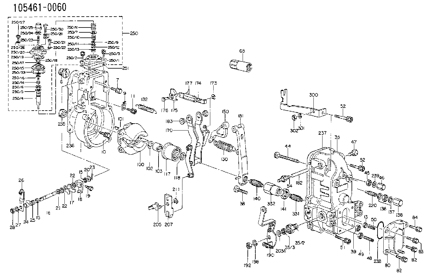
| 1. | [1] | 154000-8020 | GOVERNOR HOUSING |
| 6. | [1] | 154007-0200 | ADAPTOR |
| 7. | [1] | 020018-1640 | BLEEDER SCREW M8P1.25L16 4T |
| 9. | [1] | 154350-1800 | PLATE |
| 10. | [5] | 029010-6810 | BLEEDER SCREW |
| 11. | [1] | 020106-1640 | BLEEDER SCREW M6P1.0L14 |
| 13. | [1] | 029240-6010 | UNION NUT M6P1.0H5* |
| 15. | [2] | 029620-8050 | PACKING RING |
| 15. | [2] | 029620-8050 | PACKING RING |
| 16. | [1] | 155004-3200 | LEVER SHAFT |
| 17. | [1] | 154408-1520 | CONTROL LEVER |
| 18. | [1] | 155003-1920 | CONTROL LEVER |
| 19. | [1] | 155006-0700 | BLEEDER SCREW |
| 20. | [1] | 139308-0900 | PLAIN WASHER D16&8T1 |
| 20B. | [1] | 139308-1000 | PLAIN WASHER D16&8T1.5 |
| 21. | [1] | 016010-0740 | LOCKING WASHER |
| 22. | [0] | 029310-8040 | SHIM D13.5&8T0.2 |
| 22. | [0] | 029310-8040 | SHIM D13.5&8T0.2 |
| 22B. | [0] | 029310-8050 | SHIM D13.5&8T0.5 |
| 23. | [1] | 025520-1210 | SPLIT PIN |
| 24. | [1] | 154206-2000 | BUSHING |
| 25. | [1] | 154327-3600 | COILED SPRING |
| 26. | [1] | 154304-3820 | CONTROL LEVER |
| 27. | [1] | 014110-8440 | LOCKING WASHER |
| 28. | [1] | 013020-8040 | UNION NUT M8P1.25H7 |
| 35. | [1] | 154510-2020 | GOVERNOR COVER |
| 35/2. | [1] | 154321-1800 | BUSHING |
| 35/3. | [1] | 029621-0080 | PACKING RING |
| 38. | [1] | 154031-3200 | FLAT-HEAD SCREW |
| 39. | [1] | 154011-1600 | UNION NUT |
| 44. | [1] | 154034-0600 | FLAT-HEAD SCREW |
| 45. | [1] | 029200-8500 | UNION NUT |
| 46. | [1] | 154035-1700 | CAP NUT |
| 47. | [1] | 154036-0300 | CAPSULE |
| 48. | [1] | 154010-5400 | FLAT-HEAD SCREW |
| 49. | [1] | 029240-8000 | UNION NUT |
| 50. | [1] | 155615-1000 | FLAT-HEAD SCREW |
| 51. | [4] | 020106-3840 | BLEEDER SCREW |
| 52. | [1] | 020106-5040 | BLEEDER SCREW |
| 52. | [1] | 020106-5040 | BLEEDER SCREW |
| 54. | [1] | 154036-1100 | CAPSULE |
| 55. | [1] | 139106-0900 | BLEEDER SCREW |
| 56. | [1] | 014110-6440 | LOCKING WASHER |
| 65. | [1] | 155404-5700 | CAP |
| 80. | [1] | 154060-0020 | COVER |
| 82. | [2] | 029020-6210 | BLEEDER SCREW |
| 82. | [2] | 029020-6210 | BLEEDER SCREW |
| 83. | [1] | 020006-1640 | BLEEDER SCREW M6P1L16 4T |
| 84. | [1] | 029000-6800 | BLEEDER SCREW |
| 100. | [1] | 154100-5020 | FLYWEIGHT ASSEMBLY |
| 101. | [1] | 025803-1610 | WOODRUFF KEY |
| 102. | [1] | 029321-2020 | LOCKING WASHER |
| 103. | [1] | 029231-2030 | UNION NUT |
| 117. | [1] | 154123-1020 | SLIDING PIECE |
| 118/1. | [0] | 029311-0010 | SHIM D14&10.1T0.2 |
| 118/1. | [0] | 029311-0180 | SHIM D14&10.1T0.3 |
| 118/1. | [0] | 029311-0190 | SHIM D14&10.1T0.40 |
| 118/1. | [0] | 029311-0210 | SHIM D14&10.1T1 |
| 118/1. | [0] | 139410-0000 | SHIM D14.0&10.1T0.5 |
| 118/1. | [0] | 139410-0100 | SHIM D14.0&10.1T1.5 |
| 118/1. | [0] | 139410-3000 | SHIM D14&10.1T2.0 |
| 118/1. | [0] | 139410-3100 | SHIM D14&10.1T3.0 |
| 118/1. | [0] | 139410-3200 | SHIM D14&10.1T4.0 |
| 130. | [1] | 154150-2400 | GOVERNOR SPRING |
| 132. | [1] | 154154-1300 | COILED SPRING |
| 136. | [1] | 029201-2140 | UNION NUT |
| 137. | [2] | 026512-1540 | GASKET D15.4&12.2T1.50 |
| 138. | [1] | 154159-1200 | CAP NUT |
| 140. | [1] | 154178-2220 | HEADLESS SCREW |
| 141. | [1] | 029201-6010 | UNION NUT |
| 150. | [1] | 154200-2300 | CONTROL LEVER |
| 170. | [1] | 154216-0120 | FORK LEVER |
| 173. | [1] | 016010-0540 | LOCKING WASHER |
| 174. | [1] | 154230-5620 | STRAP |
| 175. | [1] | 154232-1100 | CONNECTOR |
| 176. | [1] | 154222-5800 | BEARING PIN |
| 177. | [1] | 155402-3800 | SAFETY PIN |
| 181. | [1] | 154236-1220 | TENSIONING LEVER |
| 182. | [1] | 154237-0400 | BEARING PIN |
| 183. | [2] | 154237-0600 | BUSHING |
| 190. | [1] | 154306-1620 | CONTROL LEVER |
| 192. | [1] | 013020-8040 | UNION NUT M8P1.25H7 |
| 198. | [1] | 014110-8440 | LOCKING WASHER |
| 203/1. | [0] | 029311-0640 | SHIM D26.0&10.2T0.95 |
| 203/1. | [0] | 029311-0650 | SHIM D26.0&10.2T0.20 |
| 203/1. | [0] | 029311-0660 | SHIM D26.0&10.2T0.25 |
| 203/1. | [0] | 029311-0670 | SHIM D26.0&10.2T0.30 |
| 203/1. | [0] | 029311-0680 | SHIM D26.0&10.2T0.35 |
| 203/1. | [0] | 029311-0690 | SHIM D26.0&10.2T0.40 |
| 203/1. | [0] | 029311-0700 | SHIM D26.0&10.2T0.50 |
| 203/1. | [0] | 139410-1400 | SHIM D26&10.2T0.7 |
| 203/1. | [0] | 139410-1500 | SHIM D26&10.2T0.9 |
| 203/1. | [0] | 139410-1600 | SHIM D26&10.2T0.8 |
| 203/1. | [0] | 139410-2700 | SHIM D26&10.2T0.6 |
| 205. | [1] | 154324-1200 | LEVER SHAFT |
| 207. | [1] | 154326-0300 | CONTROL LEVER |
| 211. | [1] | 016010-0840 | LOCKING WASHER |
| 220. | [1] | 154050-1220 | HEADLESS SCREW |
| 235. | [1] | 155412-5200 | IMPELLER WHEEL |
| 236. | [1] | 154390-0000 | GASKET |
| 237. | [1] | 154390-0300 | GASKET |
| 238. | [1] | 029635-2020 | O-RING |
| 239. | [1] | 026508-1240 | GASKET D11.9&8.2T1 |
| 250. | [1] | 154407-3220 | MANIFOLD-PRESSURE COMP. |
| 250/1. | [1] | 154408-6220 | DIAPHRAGM HOUSING |
| 250/2. | [3] | 020106-1640 | BLEEDER SCREW M6P1.0L14 |
| 250/3. | [1] | 029020-6210 | BLEEDER SCREW |
| 250/4. | [1] | 154400-5101 | STOP PIN |
| 250/5. | [1] | 153400-0700 | SLOTTED WASHER |
| 250/6. | [1] | 016010-0740 | LOCKING WASHER |
| 250/7. | [0] | 029312-0180 | SHIM D25.5&20T0.5 |
| 250/7B. | [0] | 029312-0210 | SHIM D25.5&20T0.2 |
| 250/8. | [1] | 154403-5100 | COILED SPRING |
| 250/9. | [0] | 029310-8010 | PLAIN WASHER D15&8.4T0.2 |
| 250/9B. | [0] | 029310-8020 | PLAIN WASHER D15&8.4T0.3 |
| 250/10. | [1] | 154411-0200 | COILED SPRING |
| 250/11. | [1] | 153400-0800 | SPRING SEAT |
| 250/12. | [1] | 014110-5440 | LOCKING WASHER |
| 250/13. | [1] | 013030-5240 | UNION NUT M5P0.8H3.2 |
| 250/14. | [1] | 154400-5200 | BLEEDER SCREW |
| 250/15. | [1] | 154400-0620 | DIAPHRAGM |
| 250/16. | [1] | 029330-8050 | GASKET |
| 250/17. | [1] | 014110-6440 | LOCKING WASHER |
| 250/18. | [1] | 023040-6040 | UNION NUT |
| 250/19. | [1] | 154404-3100 | PLATE |
| 250/20. | [1] | 154404-3900 | COVER |
| 250/21. | [3] | 029010-6310 | BLEEDER SCREW |
| 250/22. | [3] | 014110-6440 | LOCKING WASHER |
| 250/23. | [1] | 154404-1100 | FLAT-HEAD SCREW |
| 250/24. | [1] | 023040-6040 | UNION NUT |
| 250/25. | [1] | 154406-7800 | CAP NUT |
| 250/26. | [1] | 026506-1040 | GASKET D9.9&6.2T1 |
| 250/27. | [1] | 029010-6010 | CAPSULE M6P1.0L7 |
| 250/28. | [2] | 026510-1340 | GASKET D13.4&10.2T1 |
| 250/30. | [1] | 029731-0180 | EYE BOLT |
| 250/33. | [3] | 154413-2600 | GASKET |
| 251. | [1] | 154390-2000 | GASKET |
| 300. | [1] | 154353-4700 | BRACKET |
| 301. | [1] | 014110-6440 | LOCKING WASHER |
| 302. | [1] | 013020-6040 | UNION NUT M6P1H5 |
Cross reference number
Zexel num
Bosch num
Firm num
Name
Information:
2-302. Dismantle the vee-belt idler or cover. Slacken the screw on the injection pump drive with special spanner No. 110310.Fig. 2-30
2-31
2-323. Slowly rotate the injection pump shaft in the direction of normal rotation until the pump starts to deliver fuel. (Use double spanner No. 110330 or a 19 mm socket spanner)Fig. 2-31 and 2-324. Check that fuel comes out from overflow pipe (when operating test unit or pump) only in droplets at intervals of 5-8 seconds.5. Retain the injection pump shaft in this position and tighten the screws on the injection pump drive, using special spanner No. 110310.6. Re-check the fuel-injection point and correct, if necessary. Turn off the high-pressure tester.
2-337. Assemble the vee-belt idler or cover with a new rubber O-ring. Dismantle the timing device. Connect the fuel lines, free from tension, and assemble the cover on the injection pump.Fig. 2-33Testing The Injection Nozzle (by testing outfit)
Injector is removed.
2-341. Connect injector to outfit.Fig. 2-34
2-352. With pressure gauge cut in, press outfit pump lever several times. Read opening pressure (Fig. 2-35) and inspect spray pattern. Compare readings with Specification Data. Important:At 25 - 30 bar below specified opening pressure, check that no fuel will dribble from nozzle.
2-363. Adjust nozzle opening pressure by shims below the spring (adding shims increases pressure and vice versa). Shims of the following thicknesses are available: 1.0; 1.05; 1.1; 1.15; etc. up to 1.95 mm.Fig. 2-36 Note for Refitment:By adding shims the pressure will be increased; by removing them the pressure will be decreased.
2-37For FL 912W, adjust release pressure by means of set-screw. By turning in screw, release pressure is increased; by turning it out, pressure is decreased.Fig. 2-37
2-384. Repeat test and recheck spray pattern. The jet(s) should be solid without surrounding mist. Fig. 2-38
2-39FL 912/W: one jet onlyFig. 2-395. Check that there is no after-dribble.6. If nozzle works unsatisfactorily, replace.Testing The Injection Pump (by special outfit)
The test is confined to making sure that the delivery valves and pump elements are free from leaks. The fuel feed pump intake is connected to the fuel tank or a receptacle containing filtered fuel. Proper fuel delivery is a prerequisite.
2-401. Disconnect injection line(s) on the fuel-injection pump. Evacuate the air from the fuel injection pump. Connect the tester to the pump element to be checked.Fig. 2-40
2-412. Open the second connection of the tester and evacuate the air. When the escaping fuel is free from bubbles, close the second connection.Fig. 2-41 The manual operation of the fuel-injection pump elements differs from one type of engine to another.F2L: Rotate the crankshaft until the air is evacuated or until the pressure has built up.
2-42As from 3 cylinder engine: Lower the tappet of the element to be checked by turning the crankshaft and then pump with a lever.Fig. 2-423. To check a pressure relief valve, generate a pressure of 150 bar. The indicator of the pressure gauge may not drop back more than 10 bar during a minute.
2-434. Generate a pressure peak of 350 bar. This must be clearly indicated by