Information governor
BOSCH
F 019 Z9E 780
f019z9e780
ZEXEL
105455-1071
1054551071

Rating:
Scheme ###:
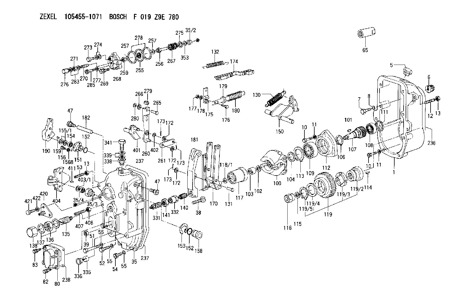
| 1. | [1] | 154003-2020 | GOVERNOR HOUSING |
| 5. | [1] | 154007-3400 | CAPSULE |
| 6. | [1] | 154007-0500 | ADAPTOR |
| 7. | [1] | 010038-1840 | BLEEDER SCREW M8P1.25L18 |
| 8. | [1] | 014110-8440 | LOCKING WASHER |
| 10. | [10] | 010038-2840 | BLEEDER SCREW |
| 10. | [10] | 010038-2840 | BLEEDER SCREW |
| 11. | [10] | 014110-8440 | LOCKING WASHER |
| 11. | [10] | 014110-8440 | LOCKING WASHER |
| 12. | [1] | 154010-9500 | FLAT-HEAD SCREW |
| 13. | [2] | 029241-0020 | UNION NUT |
| 13. | [2] | 029241-0020 | UNION NUT |
| 35. | [1] | 154522-4220 | GOVERNOR COVER |
| 35/2. | [1] | 154412-8500 | BUSHING |
| 35/3. | [1] | 154204-2800 | BUSHING |
| 35/4. | [1] | 139610-0000 | PACKING RING |
| 38. | [1] | 154031-3900 | FLAT-HEAD SCREW |
| 39. | [1] | 029201-0160 | UNION NUT |
| 47. | [2] | 154036-0400 | CAPSULE |
| 47. | [2] | 154036-0400 | CAPSULE |
| 51. | [4] | 010038-9140 | BLEEDER SCREW M8P1.25L95 |
| 52. | [2] | 139008-0500 | BLEEDER SCREW |
| 53. | [1] | 154010-9500 | FLAT-HEAD SCREW |
| 54. | [3] | 010038-2840 | BLEEDER SCREW |
| 55. | [9] | 014110-8410 | LOCKING WASHER |
| 55. | [9] | 014110-8410 | LOCKING WASHER |
| 55. | [9] | 014110-8410 | LOCKING WASHER |
| 65. | [1] | 154050-1620 | STOPPING DEVICE |
| 80. | [1] | 154063-6900 | COVER |
| 82. | [2] | 029020-6210 | BLEEDER SCREW |
| 83. | [2] | 020006-1640 | BLEEDER SCREW M6P1L16 4T |
| 100. | [1] | 154102-2420 | FLYWEIGHT ASSEMBLY |
| 101. | [1] | 025804-1610 | WOODRUFF KEY |
| 102. | [1] | 029321-4010 | LOCKING WASHER |
| 103. | [1] | 131325-2600 | UNION NUT |
| 104. | [1] | 154120-0200 | PLAIN WASHER |
| 106. | [1] | 016020-2510 | LOCKING WASHER |
| 107. | [1] | 154121-0900 | TOOTHED GEAR |
| 108. | [1] | 016630-2640 | BEARING PLATE |
| 109. | [1] | 028102-5010 | BEARING PLATE |
| 111. | [1] | 029313-2010 | SHIM D39.8&32T1 |
| 111A. | [1] | 029313-2020 | SHIM D39.8&32T0.2 |
| 112. | [1] | 154122-0200 | COVER |
| 113. | [1] | 016110-5210 | LOCKING WASHER |
| 114. | [1] | 025805-1910 | WOODRUFF KEY |
| 115. | [1] | 023641-8410 | LOCKING WASHER |
| 116. | [1] | 154011-2400 | UNION NUT |
| 117. | [1] | 154123-1820 | SLIDING PIECE |
| 118/1. | [0] | 029311-5020 | SHIM D20.5&15T0.05 |
| 118/1. | [0] | 029311-5030 | SHIM D20.5&15T0.1 |
| 118/1. | [0] | 029311-5050 | SHIM D20.5&15T0.2 |
| 118/1. | [0] | 029311-5060 | SHIM D20.5&15T0.4 |
| 118/1. | [0] | 029311-5080 | SHIM D20.5&15T0.5 |
| 118/1. | [0] | 029311-5120 | SHIM D20.5&15T0.3 |
| 119. | [1] | 154130-2320 | TOOTHED GEAR |
| 119/2. | [1] | 154132-0520 | HOLDER |
| 119/3. | [4] | 153251-1000 | DAMPER |
| 119/4. | [1] | 153321-0100 | PLAIN WASHER |
| 119/5. | [1] | 016020-4010 | LOCKING WASHER |
| 130. | [1] | 154150-9520 | GOVERNOR SPRING |
| 131. | [1] | 154356-6000 | BEARING PIN |
| 132. | [1] | 154154-4500 | COILED SPRING |
| 135. | [1] | 154158-3020 | HEADLESS SCREW |
| 136. | [1] | 139226-0000 | UNION NUT |
| 137. | [2] | 029332-6030 | GASKET |
| 138. | [1] | 154159-1600 | CAP NUT |
| 140. | [1] | 154187-0120 | HEADLESS SCREW |
| 141. | [1] | 139220-0300 | UNION NUT |
| 150. | [1] | 154200-6020 | SWIVELLING LEVER |
| 151. | [1] | 154204-3200 | BUSHING |
| 152. | [2] | 139718-0000 | O-RING |
| 152. | [2] | 139718-0000 | O-RING |
| 153. | [1] | 016010-2010 | LOCKING WASHER |
| 154. | [1] | 139614-0200 | PACKING RING |
| 155/1. | [0] | 029311-4040 | SHIM D26&14.2T0.3 |
| 155/1. | [0] | 029311-4050 | SHIM D26&14.2T0.4 |
| 155/1. | [0] | 029311-4060 | SHIM D26&14.2T0.5 |
| 155/1. | [0] | 029311-4080 | SHIM D26&14.2T0.1 |
| 156. | [2] | 154372-1800 | BLEEDER SCREW |
| 156B. | [2] | 014110-8440 | LOCKING WASHER |
| 158. | [1] | 154204-2600 | BUSHING |
| 159. | [1] | 025803-1310 | WOODRUFF KEY |
| 170. | [1] | 154217-2120 | FORK LEVER |
| 172. | [3] | 029310-6040 | SHIM |
| 172. | [3] | 029310-6040 | SHIM |
| 172. | [3] | 029310-6040 | SHIM |
| 173. | [3] | 015325-1590 | SPLIT PIN |
| 173. | [3] | 015325-1590 | SPLIT PIN |
| 173. | [3] | 015325-1590 | SPLIT PIN |
| 174. | [1] | 154234-0920 | STRAP |
| 175. | [1] | 154232-0100 | CONNECTOR |
| 176. | [1] | 010006-1840 | BLEEDER SCREW M6P1L18 4T |
| 177. | [1] | 013020-6040 | UNION NUT M6P1H5 |
| 178. | [2] | 154233-0100 | TAB WASHER |
| 179. | [1] | 153400-0200 | SLOTTED WASHER |
| 180. | [1] | 153401-0300 | COILED SPRING |
| 181. | [1] | 154236-8100 | TENSIONING LEVER |
| 182. | [1] | 154237-0300 | BEARING PIN |
| 190. | [1] | 154347-6220 | CONTROL LEVER |
| 236. | [1] | 154390-3000 | GASKET |
| 237. | [1] | 154390-3200 | GASKET |
| 237. | [1] | 154390-3200 | GASKET |
| 238. | [1] | 154390-3600 | GASKET |
| 255. | [1] | 154400-7420 | DIAPHRAGM |
| 256. | [1] | 154401-3800 | STOP PIN |
| 257. | [2] | 029330-8050 | GASKET |
| 257. | [2] | 029330-8050 | GASKET |
| 259. | [1] | 154372-7200 | HEXAGON NUT |
| 260. | [1] | 154401-3921 | STRAP |
| 261. | [1] | 154401-4320 | STRAP |
| 265. | [1] | 154222-8200 | BEARING PIN |
| 266. | [1] | 029310-5280 | SHIM D10.5&5T0.5 |
| 267. | [1] | 154402-5700 | COILED SPRING |
| 268. | [1] | 154404-5000 | COVER |
| 269. | [2] | 020106-2240 | BLEEDER SCREW |
| 270. | [1] | 154404-1100 | FLAT-HEAD SCREW |
| 271. | [1] | 013030-6040 | UNION NUT M6P1H3.6 |
| 273. | [1] | 029731-0120 | EYE BOLT |
| 274. | [2] | 029341-0110 | GASKET |
| 275. | [0] | 029312-0180 | SHIM D25.5&20T0.5 |
| 275B. | [0] | 029312-0210 | SHIM D25.5&20T0.2 |
| 276. | [1] | 154035-1600 | CAP NUT |
| 277. | [1] | 029320-6010 | LOCKING WASHER |
| 278. | [2] | 154413-2600 | GASKET |
| 279. | [1] | 154223-0100 | SLIDING PIECE |
| 280. | [1] | 026110-0510 | LOCKING WASHER |
| 283. | [2] | 026506-1040 | GASKET D9.9&6.2T1 |
| 285. | [1] | 029010-6310 | BLEEDER SCREW |
| 331. | [1] | 154187-1520 | HEADLESS SCREW |
| 332. | [1] | 139220-0400 | UNION NUT |
| 335. | [1] | 154159-1700 | UNION NUT |
| 336. | [1] | 154356-6100 | CAPSULE |
| 338. | [1] | 131002-3800 | ADAPTOR |
| 339. | [2] | 029341-2140 | GASKET |
| 341. | [1] | 139812-2300 | EYE BOLT |
| 353. | [1] | 029311-0470 | SHIM |
| 401. | [1] | 154326-8020 | CONTROL LEVER |
| 402. | [1] | 016010-0840 | LOCKING WASHER |
| 403/1. | [0] | 029311-0640 | SHIM D26.0&10.2T0.95 |
| 403/1. | [0] | 029311-0650 | SHIM D26.0&10.2T0.20 |
| 403/1. | [0] | 029311-0660 | SHIM D26.0&10.2T0.25 |
| 403/1. | [0] | 029311-0670 | SHIM D26.0&10.2T0.30 |
| 403/1. | [0] | 029311-0680 | SHIM D26.0&10.2T0.35 |
| 403/1. | [0] | 029311-0690 | SHIM D26.0&10.2T0.40 |
| 403/1. | [0] | 029311-0700 | SHIM D26.0&10.2T0.50 |
| 403/1. | [0] | 139410-1400 | SHIM D26&10.2T0.7 |
| 403/1. | [0] | 139410-1500 | SHIM D26&10.2T0.9 |
| 403/1. | [0] | 139410-1600 | SHIM D26&10.2T0.8 |
| 403/1. | [0] | 139410-2700 | SHIM D26&10.2T0.6 |
| 404. | [1] | 154380-2220 | CONTROL LEVER |
| 407. | [2] | 154010-2300 | FLAT-HEAD SCREW |
| 408. | [2] | 029240-8000 | UNION NUT |
| 411. | [1] | 025802-1010 | WOODRUFF KEY |
| 420. | [1] | 154372-6720 | BRACKET |
| 421. | [1] | 010010-2040 | BLEEDER SCREW M10P1.5L20 |
| 422. | [1] | 014111-0440 | LOCKING WASHER |
Cross reference number
Zexel num
Bosch num
Firm num
Name
105455-1071
GOVERNOR
K 14JC MECHANICAL GOVERNOR GOV RSUV(D) GOV
K 14JC MECHANICAL GOVERNOR GOV RSUV(D) GOV
Information:
Introduction
The problem that is identified below does not have a known permanent solution. Until a permanent solution is known, use the solution that is identified below.Problem
DEF heated lines can get damaged during handling or other failure modes and leak diesel exhaust fluid on Clean Emission Module (CEM) and other components.Solution
Caterpillar is aware of this problem and is recommending the following interim corrective action.
Do not operate or work on this product unless you have read and understood the instruction and warnings in the relevant Operation and Maintenance Manuals and relevant service literature. Failure to follow the instructions or heed the warnings could result in injury or death. Proper care is your responsibility.
Rework Procedure
Note: This procedure is meant for temporary repair of a DEF line to allow the machine to be safely transported to the repair shop.
Table 1
Required Parts
Part Number Part Name
473-2053 Diesel Exhaust Fluid Lines Gp (5/16th 90 degree adapter)
473-2055 Diesel Exhaust Fluid Lines Gp (5/16th straight adapter)
473-2056 Diesel Exhaust Fluid Lines Gp (3/8th 90 degree adapter)
473-2057 Diesel Exhaust Fluid Lines Gp (38th 90 Straight adapter)
Table 2
Required Tools
Part Number Part Name
1U-7648 Tube Cutter
Illustration 1 g06433660
Cut the connector end on the corrugated section with the cutter.
Illustration 2 g06433665
Cut the two wires with a tie cutter.
Illustration 3 g06433668
Use a knife or sharp blade to cut the outer sheathing off. Ensure not to cut or damage the inner fluid hose.
Illustration 4 g06433669
Install the hose clamp provided first before installing the connector. Use appropriate size (3/8th or 5/16th) and type (90 degree or straight) fitting.
Illustration 5 g06433672
Fasten the clamp until the two jaws are either in contact or about 2 to 3 mm (0.08 to 0.1 inch) apart.