Information governor
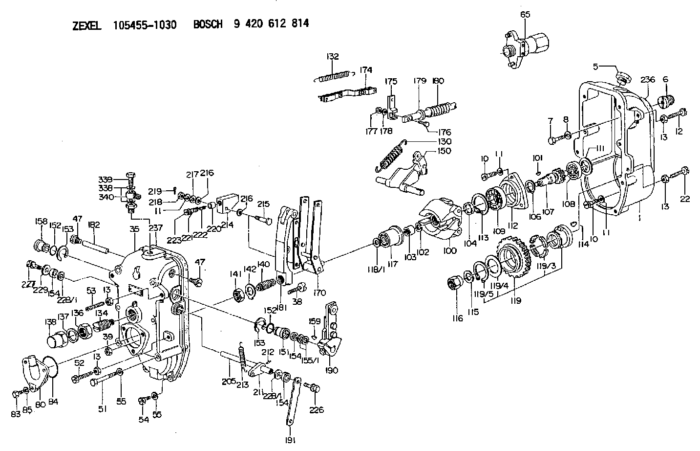
BOSCH
9 420 612 814
9420612814
ZEXEL
105455-1030
1054551030
Rating:
Scheme ###:
| 1. | [1] | 154003-2420 | GOVERNOR HOUSING |
| 5. | [1] | 154007-1400 | CAPSULE |
| 6. | [1] | 154007-3600 | ADAPTOR |
| 7. | [1] | 010038-1840 | BLEEDER SCREW M8P1.25L18 |
| 8. | [1] | 014110-8440 | LOCKING WASHER |
| 10. | [10] | 010038-2840 | BLEEDER SCREW |
| 10. | [10] | 010038-2840 | BLEEDER SCREW |
| 11. | [10] | 014110-8440 | LOCKING WASHER |
| 11. | [10] | 014110-8440 | LOCKING WASHER |
| 11. | [10] | 014110-8440 | LOCKING WASHER |
| 12. | [1] | 154034-2100 | BLEEDER SCREW |
| 13. | [4] | 029241-0020 | UNION NUT |
| 13. | [4] | 029241-0020 | UNION NUT |
| 13. | [4] | 029241-0020 | UNION NUT |
| 13. | [4] | 029241-0020 | UNION NUT |
| 22. | [1] | 154034-0400 | BLEEDER SCREW |
| 35. | [1] | 154522-0920 | GOVERNOR COVER |
| 38. | [1] | 154031-0400 | FLAT-HEAD SCREW |
| 39. | [1] | 029201-0160 | UNION NUT |
| 47. | [2] | 154036-2200 | CAPSULE |
| 47. | [2] | 154036-2200 | CAPSULE |
| 51. | [6] | 010038-9140 | BLEEDER SCREW M8P1.25L95 |
| 52. | [1] | 154034-0400 | BLEEDER SCREW |
| 53. | [1] | 154010-1800 | FLAT-HEAD SCREW |
| 54. | [2] | 010038-2840 | BLEEDER SCREW |
| 55. | [8] | 014110-8410 | LOCKING WASHER |
| 55. | [8] | 014110-8410 | LOCKING WASHER |
| 65. | [1] | 133510-2920 | STOPPING DEVICE |
| 80. | [1] | 154060-8200 | COVER |
| 83. | [3] | 020508-1840 | BLEEDER SCREW M8P1.25L18 |
| 84. | [1] | 029635-5010 | O-RING |
| 85. | [3] | 014110-8410 | LOCKING WASHER |
| 100. | [1] | 154102-1720 | FLYWEIGHT ASSEMBLY |
| 101. | [1] | 025804-1610 | WOODRUFF KEY |
| 102. | [1] | 029321-4010 | LOCKING WASHER |
| 103. | [1] | 131325-2600 | UNION NUT |
| 104. | [1] | 154120-0200 | PLAIN WASHER |
| 106. | [1] | 016020-2510 | LOCKING WASHER |
| 107. | [1] | 154121-0700 | TOOTHED GEAR |
| 108. | [1] | 016630-2640 | BEARING PLATE |
| 109. | [1] | 028102-5010 | BEARING PLATE |
| 111. | [1] | 029313-2010 | SHIM D39.8&32T1 |
| 111A. | [1] | 029313-2020 | SHIM D39.8&32T0.2 |
| 112. | [1] | 154122-0200 | COVER |
| 113. | [1] | 016110-5210 | LOCKING WASHER |
| 114. | [1] | 025805-1910 | WOODRUFF KEY |
| 115. | [1] | 023641-8410 | LOCKING WASHER |
| 116. | [1] | 154011-0200 | UNION NUT |
| 117. | [1] | 154123-1820 | SLIDING PIECE |
| 118/1. | [0] | 029311-5020 | SHIM D20.5&15T0.05 |
| 118/1. | [0] | 029311-5030 | SHIM D20.5&15T0.1 |
| 118/1. | [0] | 029311-5050 | SHIM D20.5&15T0.2 |
| 118/1. | [0] | 029311-5060 | SHIM D20.5&15T0.4 |
| 118/1. | [0] | 029311-5080 | SHIM D20.5&15T0.5 |
| 118/1. | [0] | 029311-5120 | SHIM D20.5&15T0.3 |
| 119. | [1] | 154130-0720 | TOOTHED GEAR |
| 119/3. | [4] | 153251-0200 | DAMPER |
| 119/4. | [1] | 153321-0100 | PLAIN WASHER |
| 119/5. | [1] | 016020-4010 | LOCKING WASHER |
| 130. | [1] | 154150-3300 | GOVERNOR SPRING |
| 132. | [1] | 154154-1800 | COILED SPRING |
| 134. | [1] | 154157-3320 | HEADLESS SCREW |
| 136. | [1] | 029203-0010 | UNION NUT |
| 137. | [2] | 026530-3640 | GASKET |
| 138. | [1] | 154159-0200 | CAP NUT |
| 140. | [1] | 154170-0320 | HEADLESS SCREW |
| 141. | [1] | 029202-0010 | UNION NUT |
| 142. | [1] | 154008-0200 | TAB WASHER |
| 150. | [1] | 154200-1521 | SWIVELLING LEVER |
| 151. | [1] | 154204-0301 | BUSHING |
| 152. | [2] | 029632-1010 | O-RING |
| 152. | [2] | 029632-1010 | O-RING |
| 153. | [2] | 016010-2010 | LOCKING WASHER |
| 153. | [2] | 016010-2010 | LOCKING WASHER |
| 154. | [3] | 029621-4000 | PACKING RING |
| 154. | [3] | 029621-4000 | PACKING RING |
| 154. | [3] | 029621-4000 | PACKING RING |
| 155/1. | [0] | 029311-4040 | SHIM D26&14.2T0.3 |
| 155/1. | [0] | 029311-4050 | SHIM D26&14.2T0.4 |
| 155/1. | [0] | 029311-4060 | SHIM D26&14.2T0.5 |
| 155/1. | [0] | 029311-4080 | SHIM D26&14.2T0.1 |
| 158. | [1] | 154204-3800 | BUSHING |
| 159. | [1] | 025803-1310 | WOODRUFF KEY |
| 170. | [1] | 154211-4820 | FORK LEVER |
| 174. | [1] | 154230-1620 | STRAP |
| 175. | [1] | 154232-0100 | CONNECTOR |
| 176. | [1] | 010006-1840 | BLEEDER SCREW M6P1L18 4T |
| 177. | [1] | 013020-6040 | UNION NUT M6P1H5 |
| 178. | [2] | 154233-0100 | TAB WASHER |
| 179. | [1] | 153400-0200 | SLOTTED WASHER |
| 180. | [1] | 153401-0300 | COILED SPRING |
| 181. | [1] | 154236-0800 | TENSIONING LEVER |
| 182. | [1] | 154237-0300 | BEARING PIN |
| 190. | [1] | 154303-4520 | CONTROL LEVER |
| 191. | [1] | 154300-0300 | CONTROL LEVER |
| 205. | [1] | 154330-1500 | LEVER SHAFT |
| 211. | [1] | 154331-0100 | CONTROL LEVER |
| 212. | [1] | 024330-2030 | BEARING PIN |
| 213. | [1] | 154332-0100 | COILED SPRING |
| 214. | [1] | 154333-0200 | CONTROL LEVER |
| 215. | [1] | 154334-0100 | BEARING PIN |
| 216. | [2] | 029301-0030 | PLAIN WASHER |
| 216. | [2] | 029301-0030 | PLAIN WASHER |
| 217. | [1] | 029300-8070 | PLAIN WASHER |
| 218. | [1] | 013020-8020 | UNION NUT M8P1.25H7 |
| 219. | [4] | 025520-1210 | SPLIT PIN |
| 220. | [1] | 154335-0100 | SLOTTED WASHER |
| 221. | [1] | 154336-0100 | COILED SPRING |
| 222. | [1] | 154336-0200 | COILED SPRING |
| 223. | [1] | 154337-0100 | CAPSULE |
| 226. | [1] | 021306-1540 | FLAT-HEAD SCREW |
| 227. | [1] | 020006-1640 | BLEEDER SCREW M6P1L16 4T |
| 228/1. | [0] | 029311-4040 | SHIM D26&14.2T0.3 |
| 228/1. | [0] | 029311-4050 | SHIM D26&14.2T0.4 |
| 228/1. | [0] | 029311-4060 | SHIM D26&14.2T0.5 |
| 228/1. | [0] | 029311-4060 | SHIM D26&14.2T0.5 |
| 228/1. | [0] | 029311-4080 | SHIM D26&14.2T0.1 |
| 229. | [1] | 154350-0700 | PLATE |
| 236. | [1] | 154390-3000 | GASKET |
| 237. | [1] | 154390-3300 | GASKET |
| 338. | [2] | 029340-6120 | GASKET |
| 339. | [1] | 139806-0000 | EYE BOLT |
| 340. | [1] | 139806-0200 | INLET UNION |
Include in #1:
103682-0480
as GOVERNOR
Cross reference number
Zexel num
Bosch num
Firm num
Name
Information:
Personal injury can result from improper handling of chemicals.Make sure you use all the necessary protective equipment required to do the job.Make sure that you read and understand all directions and hazards described on the labels and material safety data sheet of any chemical that is used.Observe all safety precautions recommended by the chemical manufacturer for handling, storage, and disposal of chemicals.
C175 Engine References
Reference: Troubleshooting, M0069788, "C175 Tier 4 Final Engines for Off-Highway Trucks"Reference: Testing and Adjusting, M0069782, "C175 Tier 4 Final Engines for Off-Highway Trucks"Reference: Disassembly and Assembly, M0080117, "C175 Tier 4 Final Engines for Caterpillar Built Machines"3500 Engine References
Reference: Troubleshooting, M0080819, "3516E Engine for Tier 4 Final 994K Wheel Loaders"Reference: Testing and Adjusting, M0080815, "3516E Engine for Tier 4 Final 994K Wheel Loaders"Reference: Disassembly and Assembly, M0092351, "3516E Engines for Caterpillar Built Machines"Procedure
Note: If failed parts need to be shipped back, please cap off the ports using the caps from the new part.
The DEF injector troubleshooting return form is required and included with failed part returns documenting what was found that led to DEF injector replacement. Attach photos of the DEF injector tip and the mount area along with a Product Status Report to the Service Information Management System claim.
Determine the diagnostic code. ____________________
Troubleshoot the code found using the appropriate troubleshooting manual.
When the troubleshooting procedure requests the DEF quality check, DEF injector resistance measurement, or Dosing Accuracy Test, document the results in Tables 1, 2, and 3.
Table 1
DEF Quality Results
Step Instruction Completed (Yes/No) Units
1 Follow the Testing and Adjusting procedure for "Diesel Exhaust Fluid Quality - Test"
2 DEF Contamination Test (include photo of test strip if possible)
3 DEF Concentration Test
% at 20° C (68° F)
Illustration 1 g06371891
Diesel Exhaust Fluid (DEF) Injector Resistance Measurement
Table 2
Injector Resistance Measurement
Step Instruction Completed (Yes/No) Units
1 Turn the keyswitch to the OFF position. Allow 2 minutes to elapse before proceeding.
2 Disconnect the DEF injector from the applicable harness.
3 Inspect the connector for damage or debris (if damaged take photo).
4 Measure the temperature of the injector (aluminum body). ° C (° F)
5 Connect 2 of the 398-4987 Probe to the DEF injector. The connectors must be used to prevent damage to the DEF injector connector.
6 Measure the resistance of the DEF injector.
Ohms
Table 3
Dosing Accuracy Test
Step Instruction Completed (Yes/No) Units
1 Follow the Testing and Adjusting, Aftertreatment SCR System Dosing - Test.
2 Take a photograph of the DEF injector mount, gasket, and bolts on the SCR inlet prior to removal.
3 Remove the injector from the SCR inlet.
4 Take a photograph of the DEF injector mount on the SCR inlet and the tip of the DEF injector. ° C (° F)
5 Run the DEF System Dosing Accuracy test through Cat ET.
6 Use a beaker to measure the amount of fluid from the dosing test. mL (oz)
7 Repeat the test to verify consistency.
mL (oz)
8 Install the injector back onto the SCR Inlet if instructed per the Troubleshooting Guide Results/Comments
____________________________________________________________________________________________________________________________________________________________________________________________________________________________________________________________________________________________________________________________________________________________________________________________________________________________________________________________________________________________________________________________________________________________________________________________________________________________________________