Information governor
BOSCH
F 019 Z1E 882
f019z1e882
ZEXEL
105455-0020
1054550020
Rating:
Scheme ###:
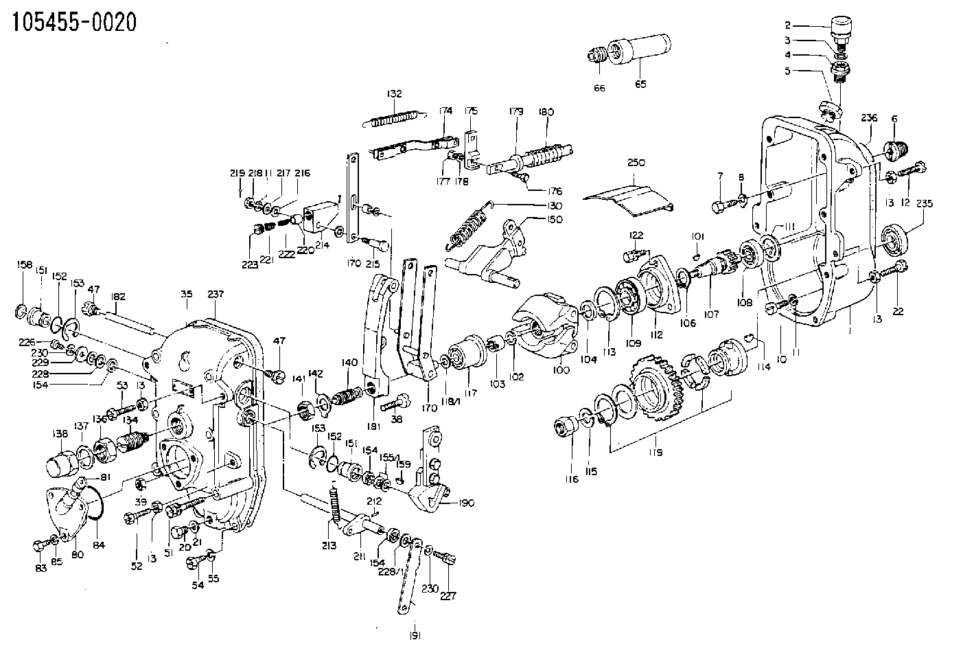
| 1. | [1] | 154003-0920 | GOVERNOR HOUSING |
| 2. | [1] | 155406-0620 | AIR FILTER |
| 3. | [1] | 026512-1540 | GASKET D15.4&12.2T1.50 |
| 4. | [1] | 154007-0100 | ADAPTOR |
| 5. | [1] | 154007-1400 | CAPSULE |
| 6. | [1] | 154007-0500 | ADAPTOR |
| 7. | [1] | 010038-1840 | BLEEDER SCREW M8P1.25L18 |
| 8. | [1] | 154008-0100 | TAB WASHER |
| 10. | [4] | 010508-2540 | FLAT-HEAD SCREW M8P1.25L25 |
| 11. | [9] | 014110-8410 | LOCKING WASHER |
| 11. | [9] | 014110-8410 | LOCKING WASHER |
| 12. | [1] | 154010-6200 | BLEEDER SCREW |
| 13. | [4] | 029241-0020 | UNION NUT |
| 13. | [4] | 029241-0020 | UNION NUT |
| 13. | [4] | 029241-0020 | UNION NUT |
| 13. | [4] | 029241-0020 | UNION NUT |
| 20. | [1] | 029111-0030 | CAPSULE |
| 21. | [1] | 026510-1340 | GASKET D13.4&10.2T1 |
| 22. | [1] | 154034-0400 | BLEEDER SCREW |
| 35. | [1] | 154522-0120 | GOVERNOR COVER |
| 38. | [1] | 154031-0400 | FLAT-HEAD SCREW |
| 39. | [1] | 029201-0160 | UNION NUT |
| 47. | [2] | 154036-0400 | CAPSULE |
| 47. | [2] | 154036-0400 | CAPSULE |
| 51. | [6] | 010038-9140 | BLEEDER SCREW M8P1.25L95 |
| 52. | [1] | 154034-0400 | BLEEDER SCREW |
| 53. | [1] | 154010-1800 | FLAT-HEAD SCREW |
| 54. | [2] | 010038-2840 | BLEEDER SCREW |
| 55. | [8] | 014110-8410 | LOCKING WASHER |
| 80. | [1] | 154060-0520 | COVER |
| 81. | [1] | 133030-0520 | LEVEL INDICATOR |
| 83. | [3] | 020508-1840 | BLEEDER SCREW M8P1.25L18 |
| 84. | [1] | 029635-5010 | O-RING |
| 85. | [3] | 014110-8410 | LOCKING WASHER |
| 100. | [1] | 154102-1720 | FLYWEIGHT ASSEMBLY |
| 101. | [1] | 025804-1610 | WOODRUFF KEY |
| 102. | [1] | 029321-4010 | LOCKING WASHER |
| 103. | [1] | 131325-2600 | UNION NUT |
| 104. | [1] | 154120-0200 | PLAIN WASHER |
| 106. | [1] | 016020-2510 | LOCKING WASHER |
| 107. | [1] | 154121-0600 | TOOTHED GEAR |
| 108. | [1] | 016630-2640 | BEARING PLATE |
| 109. | [1] | 028102-5010 | BEARING PLATE |
| 111. | [1] | 029313-2010 | SHIM D39.8&32T1 |
| 111A. | [1] | 029313-2020 | SHIM D39.8&32T0.2 |
| 112. | [1] | 154122-0200 | COVER |
| 113. | [1] | 016110-5210 | LOCKING WASHER |
| 114. | [1] | 025805-1910 | WOODRUFF KEY |
| 115. | [1] | 023641-8410 | LOCKING WASHER |
| 116. | [1] | 154011-0200 | UNION NUT |
| 117. | [1] | 154123-1820 | SLIDING PIECE |
| 118/1. | [0] | 029311-5020 | SHIM D20.5&15T0.05 |
| 118/1. | [0] | 029311-5030 | SHIM D20.5&15T0.1 |
| 118/1. | [0] | 029311-5050 | SHIM D20.5&15T0.2 |
| 118/1. | [0] | 029311-5060 | SHIM D20.5&15T0.4 |
| 118/1. | [0] | 029311-5080 | SHIM D20.5&15T0.5 |
| 118/1. | [0] | 029311-5120 | SHIM D20.5&15T0.3 |
| 119. | [1] | 154130-0620 | TOOTHED GEAR |
| 119/2. | [1] | 154132-0220 | HOLDER |
| 119/3. | [4] | 153251-0200 | DAMPER |
| 119/4. | [1] | 153321-0100 | PLAIN WASHER |
| 119/5. | [1] | 016020-4010 | LOCKING WASHER |
| 122. | [4] | 020308-2540 | BLEEDER SCREW M8P1.25L25 |
| 130. | [1] | 154150-4700 | GOVERNOR SPRING |
| 132. | [1] | 154154-1800 | COILED SPRING |
| 134. | [1] | 154157-0520 | HEADLESS SCREW |
| 136. | [1] | 029203-0010 | UNION NUT |
| 137. | [2] | 026530-3640 | GASKET |
| 138. | [1] | 154159-0200 | CAP NUT |
| 150. | [1] | 154200-1521 | SWIVELLING LEVER |
| 151. | [1] | 154204-0301 | BUSHING |
| 151. | [1] | 154204-0301 | BUSHING |
| 152. | [2] | 029632-1010 | O-RING |
| 152. | [2] | 029632-1010 | O-RING |
| 153. | [2] | 016010-2010 | LOCKING WASHER |
| 153. | [2] | 016010-2010 | LOCKING WASHER |
| 154. | [3] | 029621-4000 | PACKING RING |
| 154. | [3] | 029621-4000 | PACKING RING |
| 154. | [3] | 029621-4000 | PACKING RING |
| 155/1. | [0] | 029311-4040 | SHIM D26&14.2T0.3 |
| 155/1. | [0] | 029311-4050 | SHIM D26&14.2T0.4 |
| 155/1. | [0] | 029311-4060 | SHIM D26&14.2T0.5 |
| 155/1. | [0] | 029311-4080 | SHIM D26&14.2T0.1 |
| 158. | [1] | 154204-3800 | BUSHING |
| 159. | [1] | 025803-1310 | WOODRUFF KEY |
| 170. | [1] | 154211-4920 | FORK LEVER |
| 170. | [1] | 154211-4920 | FORK LEVER |
| 174. | [1] | 154230-1520 | STRAP |
| 175. | [1] | 154232-0100 | CONNECTOR |
| 176. | [1] | 010006-1840 | BLEEDER SCREW M6P1L18 4T |
| 177. | [1] | 013020-6040 | UNION NUT M6P1H5 |
| 178. | [2] | 154233-0100 | TAB WASHER |
| 179. | [1] | 153400-0200 | SLOTTED WASHER |
| 180. | [1] | 153401-0300 | COILED SPRING |
| 181. | [1] | 154236-1700 | TENSIONING LEVER |
| 182. | [1] | 154237-0300 | BEARING PIN |
| 190. | [1] | 154303-4520 | CONTROL LEVER |
| 191. | [1] | 154300-0300 | CONTROL LEVER |
| 205. | [1] | 154330-1400 | LEVER SHAFT |
| 211. | [1] | 154331-0100 | CONTROL LEVER |
| 212. | [1] | 024330-2030 | BEARING PIN |
| 213. | [1] | 154332-0100 | COILED SPRING |
| 214. | [1] | 154333-0200 | CONTROL LEVER |
| 215. | [1] | 154334-0100 | BEARING PIN |
| 216. | [2] | 029301-0030 | PLAIN WASHER |
| 217. | [1] | 029300-8070 | PLAIN WASHER |
| 218. | [1] | 013020-8020 | UNION NUT M8P1.25H7 |
| 219. | [1] | 025520-1210 | SPLIT PIN |
| 220. | [1] | 154335-0100 | SLOTTED WASHER |
| 221. | [1] | 154336-0100 | COILED SPRING |
| 222. | [1] | 154336-0200 | COILED SPRING |
| 223. | [1] | 154337-0100 | CAPSULE |
| 226. | [1] | 021306-1540 | FLAT-HEAD SCREW |
| 227. | [1] | 020006-1640 | BLEEDER SCREW M6P1L16 4T |
| 228/1. | [0] | 029311-4040 | SHIM D26&14.2T0.3 |
| 228/1. | [0] | 029311-4040 | SHIM D26&14.2T0.3 |
| 228/1. | [0] | 029311-4050 | SHIM D26&14.2T0.4 |
| 228/1. | [0] | 029311-4060 | SHIM D26&14.2T0.5 |
| 228/1. | [0] | 029311-4080 | SHIM D26&14.2T0.1 |
| 229. | [1] | 154350-0700 | PLATE |
| 235. | [1] | 029622-5010 | PACKING RING |
| 236. | [1] | 154350-1000 | GASKET |
| 237. | [1] | 154390-3300 | GASKET |
| 250. | [1] | 154351-0520 | PLATE |
Cross reference number
Zexel num
Bosch num
Firm num
Name
105455-0020
GOVERNOR
K 14JC MECHANICAL GOVERNOR GOV RSUV(D) GOV
K 14JC MECHANICAL GOVERNOR GOV RSUV(D) GOV
Information:
Personal injury or death can result from improper maintenance procedures. To avoid injury or death, follow the procedures exactly as stated below.
Before servicing/performing maintenance on the machine, electrical power must be physically disconnected; battery plugs must be disconnected from the batteries, or the trailing cable must be unplugged, and warning tags and padlocks shall be applied by a certified electrician. Certified electricians shall perform or direct any electrical work, including any energized testing, repair work in controllers, motors, or other approved compartments, and shall insure that all compartments are properly closed and inspected prior to re-energization. All applicable lock out and tag out procedures must be followed.
Do not operate the machine if any guards or covers are missing or inadequately secured. Personnel could be seriously injured or machine damage may occur.
Observe the safe working load limits of all lifting and blocking devices and keep a safe distance from suspended/blocked loads. Personnel may be seriously injured or killed by falling loads.
Required Parts
Table 2
Required Parts
Item Qty Part Number Part Name
1 1 574-7991 Film Field Rework Procedure
Illustration 1 g06471195
DEF injector hose connector contacting the clearance hole
Visually inspect the DEF injector clearance hole for evidence of rub and wear for the DEF injector hose connector.
Illustration 2 g06480781
Clearance hole before grinding
Illustration 3 g06471198
Detail of area A
(D1) 12.1 mm (0.48 inch)
(D2) 75 mm (2.9 inch)
(D3) 50 mm (1.96 inch)
Illustration 4 g06471200
(D4) 50 mm (1.96 inch)
(D5) 12.6 mm (0.49 inch)
(D6) 11.7 mm (0.46 inch)
(D7) 75 mm (2.9 inch)
(D8) Radius is 35 mm (1.4 inch)
If evidence of contact is found, remove the hose connector from the DEF injector. Use die-grinder to increase size of the clearance hole from outside of the machine. Refer to the dimensions that are provided in Illustration 3 and Illustration 4.Note: To prevent unexpected lowering of the lift arms, use a lift arm safety brace to lock the lift arms in raised position. Refer to Operation and Maintenance Manual , SEBU9084 , "Loader Lift Arm Brace Operation".
Illustration 5 g06471201
DEF hose reconnected to outer connector
After the clearance hole is increased, connect the hose connector for DEF to the outer connector on the DEF injector. Verify the clearance between the frame and the DEF hose connector.
Illustration 6 g06471202
Increased clearance hole
Rotate hose connector towards front of machine. Refer to Illustration 6 for proper orientation. The increased hole is large enough to provide clearance for the hose connector.
Illustration 7 g06471206
(1) 574-7991 Film
Paint any bare metal to prevent rust and cover the clearance hole with film (1).