Information governor
BOSCH
F 019 Z1E 881
f019z1e881
ZEXEL
105453-0500
1054530500
Rating:
Scheme ###:
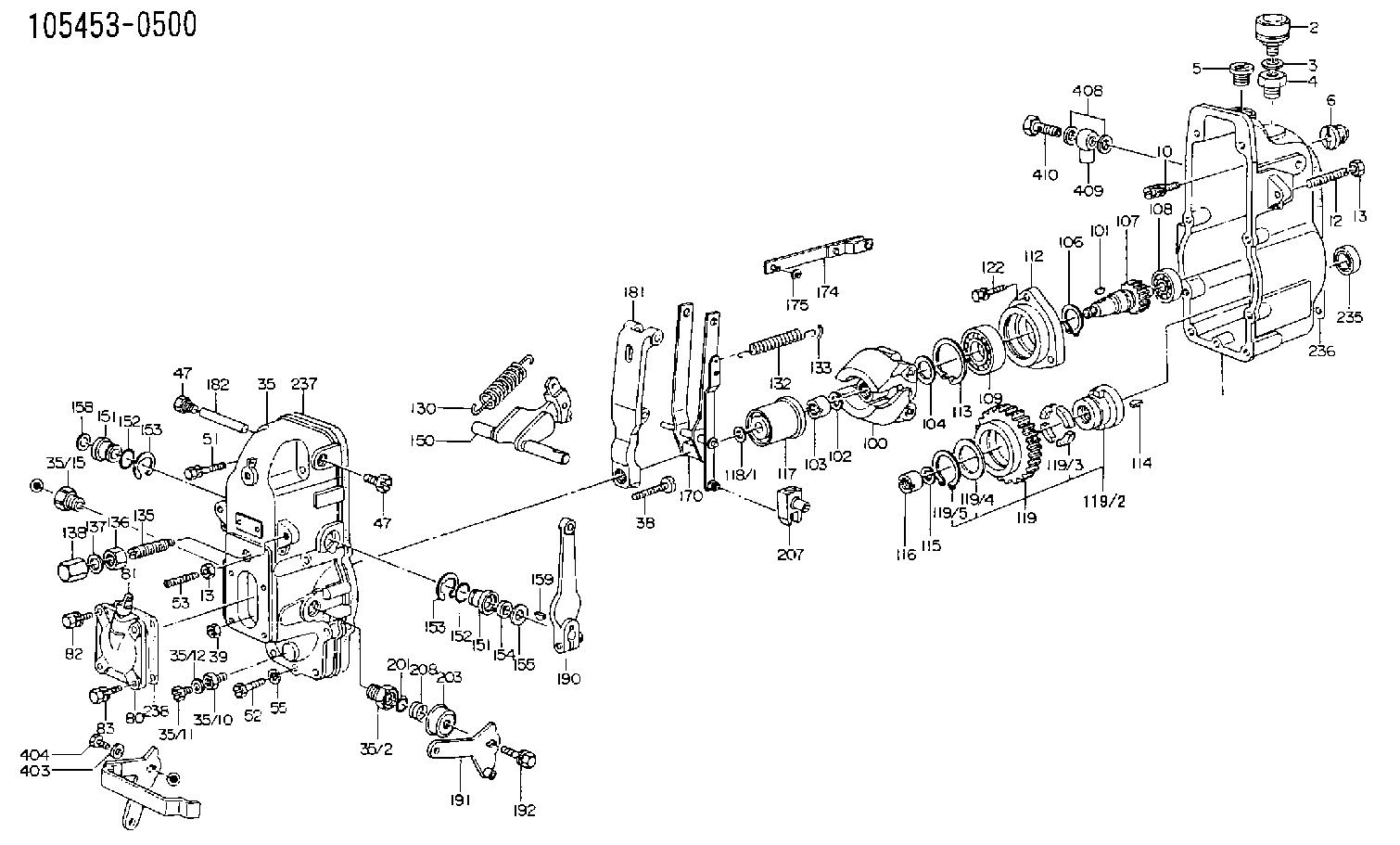
| 1. | [1] | 154002-2120 | GOVERNOR HOUSING |
| 2. | [1] | 155406-0220 | AIR FILTER |
| 3. | [1] | 026512-1540 | GASKET D15.4&12.2T1.50 |
| 4. | [1] | 154007-2700 | ADAPTOR |
| 5. | [1] | 154007-1600 | CAPSULE |
| 6. | [1] | 154007-0500 | ADAPTOR |
| 7. | [1] | 029000-8440 | BLEEDER SCREW |
| 10. | [4] | 020106-2040 | BLEEDER SCREW M6P1L20 |
| 12. | [1] | 154010-0200 | FLAT-HEAD SCREW |
| 13. | [2] | 154011-0100 | HEXAGON NUT |
| 13. | [2] | 154011-0100 | HEXAGON NUT |
| 35. | [1] | 154520-2520 | GOVERNOR COVER |
| 35/2. | [1] | 154321-0200 | BUSHING |
| 35/10. | [1] | 155012-0700 | ADAPTOR |
| 35/11. | [1] | 029010-6010 | CAPSULE M6P1.0L7 |
| 35/12. | [1] | 026506-1040 | GASKET D9.9&6.2T1 |
| 35/15. | [1] | 154321-1400 | BUSHING |
| 38. | [1] | 154031-0100 | FLAT-HEAD SCREW |
| 39. | [1] | 013020-6020 | UNION NUT M6P1H5 |
| 47. | [2] | 154036-0300 | CAPSULE |
| 47. | [2] | 154036-0300 | CAPSULE |
| 51. | [4] | 029000-6470 | BLEEDER SCREW |
| 52. | [3] | 029010-6090 | BLEEDER SCREW |
| 53. | [1] | 154010-0300 | FLAT-HEAD SCREW |
| 55. | [7] | 029320-6010 | LOCKING WASHER |
| 80. | [1] | 154060-0720 | COVER |
| 81. | [1] | 131030-2520 | LEVEL INDICATOR |
| 82. | [2] | 029020-6210 | BLEEDER SCREW |
| 83. | [2] | 020006-1640 | BLEEDER SCREW M6P1L16 4T |
| 100. | [1] | 154100-6520 | FLYWEIGHT ASSEMBLY |
| 101. | [1] | 025803-1610 | WOODRUFF KEY |
| 102. | [1] | 029321-2020 | LOCKING WASHER |
| 103. | [1] | 029231-2030 | UNION NUT |
| 104. | [1] | 154120-0100 | PLAIN WASHER |
| 106. | [1] | 029602-0020 | LOCKING WASHER |
| 107. | [1] | 154121-0200 | TOOTHED GEAR |
| 108. | [1] | 016610-2640 | BEARING PLATE |
| 109. | [1] | 028102-0010 | BEARING PLATE |
| 112. | [1] | 154122-0100 | COVER |
| 113. | [1] | 029614-7020 | LOCKING WASHER |
| 114. | [1] | 025804-1610 | WOODRUFF KEY |
| 115. | [1] | 029321-4010 | LOCKING WASHER |
| 116. | [1] | 131325-2600 | UNION NUT |
| 117. | [1] | 154123-1920 | SLIDING PIECE |
| 118/1. | [0] | 029311-0010 | SHIM D14&10.1T0.2 |
| 118/1. | [0] | 029311-0180 | SHIM D14&10.1T0.3 |
| 118/1. | [0] | 029311-0190 | SHIM D14&10.1T0.40 |
| 118/1. | [0] | 029311-0210 | SHIM D14&10.1T1 |
| 118/1. | [0] | 139410-0000 | SHIM D14.0&10.1T0.5 |
| 118/1. | [0] | 139410-0100 | SHIM D14.0&10.1T1.5 |
| 118/1. | [0] | 139410-3000 | SHIM D14&10.1T2.0 |
| 118/1. | [0] | 139410-3100 | SHIM D14&10.1T3.0 |
| 118/1. | [0] | 139410-3200 | SHIM D14&10.1T4.0 |
| 119. | [1] | 154130-0220 | TOOTHED GEAR |
| 119/2. | [1] | 154132-0120 | HOLDER |
| 119/3. | [4] | 153251-0100 | DAMPER |
| 119/4. | [1] | 139329-0000 | PLAIN WASHER |
| 119/5. | [1] | 016020-2810 | LOCKING WASHER |
| 122. | [3] | 020106-2840 | BLEEDER SCREW |
| 130. | [1] | 154150-4600 | GOVERNOR SPRING |
| 132. | [1] | 154154-0900 | COILED SPRING |
| 133. | [2] | 154156-0100 | TUBE |
| 135. | [1] | 154157-5420 | HEADLESS SCREW |
| 136. | [1] | 029201-2030 | UNION NUT M12P1.0H4 |
| 137. | [2] | 026512-1540 | GASKET D15.4&12.2T1.50 |
| 138. | [1] | 154159-0100 | CAP NUT |
| 150. | [1] | 154200-0521 | SWIVELLING LEVER |
| 151. | [1] | 154204-0201 | BUSHING |
| 151. | [1] | 154204-0201 | BUSHING |
| 152. | [2] | 029631-8020 | O-RING |
| 152. | [2] | 029631-8020 | O-RING |
| 153. | [2] | 016010-1640 | LOCKING WASHER |
| 153. | [2] | 016010-1640 | LOCKING WASHER |
| 154. | [1] | 029621-1010 | PACKING RING |
| 155. | [1] | 029311-1020 | PLAIN WASHER D16&11T1 |
| 156. | [0] | 154206-0200 | PLAIN WASHER D19.5&11.2T1.0 |
| 158. | [1] | 154204-3600 | BUSHING |
| 159. | [1] | 025803-1310 | WOODRUFF KEY |
| 170. | [1] | 154211-5420 | FORK LEVER |
| 174. | [1] | 154230-0220 | STRAP |
| 175. | [1] | 016010-0540 | LOCKING WASHER |
| 181. | [1] | 154236-1400 | TENSIONING LEVER |
| 182. | [1] | 154237-0200 | BEARING PIN |
| 190. | [1] | 154309-1420 | CONTROL LEVER |
| 191. | [1] | 154302-3020 | CONTROL LEVER |
| 192. | [1] | 020006-1640 | BLEEDER SCREW M6P1L16 4T |
| 201. | [1] | 029630-9050 | O-RING |
| 203. | [1] | 154322-0100 | CAP |
| 207. | [1] | 154326-5020 | CONTROL LEVER |
| 208. | [1] | 154327-7600 | COILED SPRING |
| 235. | [1] | 029622-0040 | PACKING RING |
| 236. | [1] | 154350-8600 | GASKET |
| 237. | [1] | 154371-3500 | GASKET |
| 238. | [1] | 154390-3600 | GASKET |
| 403. | [1] | 029300-8030 | PLAIN WASHER D15&8T1.50 |
| 404. | [1] | 154324-2000 | BLEEDER SCREW |
| 408. | [2] | 026510-1340 | GASKET D13.4&10.2T1 |
| 409. | [1] | 029701-0260 | INLET UNION |
| 410. | [1] | 029731-0040 | EYE BOLT |
Include in #1:
102672-1360
as GOVERNOR
Cross reference number
Zexel num
Bosch num
Firm num
Name
105453-0500
GOVERNOR
K 14JC MECHANICAL GOVERNOR GOV RSUV(D) GOV
K 14JC MECHANICAL GOVERNOR GOV RSUV(D) GOV
Information:
Safety Section
Care must be taken to ensure that fluids are contained during performance of inspection, maintenance, testing, adjusting, and repair of the product. Be prepared to collect the fluid with suitable containers before opening any compartment or disassembling any component containing fluids.Refer to Special Publication, NENG2500, "Dealer Service Tool Catalog" for tools and supplies suitable to collect and contain fluids on Cat® products.Dispose of all fluids according to local regulations and mandates.
Illustration 1 g00104545Prevent the machine from movement. Park the machine on a level surface.Attach a "Do Not Operate" warning tag or a similar warning tag to the start switch or to the controls before you service the equipment. These warning tags (Special Instruction, SEHS7332) are available from your Caterpillar dealer.Required Parts
Table 1 contains the parts needed to complete the installation of the new DEF filter.Note: Only one DEF filter group is required per engine. Use Table 2 to determine which filter is the appropriate filter for each DEF header. Illustration 2 shows the location of the DEF header part number.
Table 1
Part Number Part Description Qty
378-3187 Diesel Exhaust Fluid Filter Gp 1
423-3251 Connector 1
391-5262 Gasket 1
425-0385 Filter As 1
452-6055 Filter Base As 1
453-1604(1) Diesel Exhaust Fluid Filter Gp 1
453-1605(1) Diesel Exhaust Fluid Filter Gp 1
453-1606(1) Diesel Exhaust Fluid Filter Gp 1
(1) Use Table 2 to choose the correct part that corresponds to the DEF header
Illustration 2 g03745839
(1) Location of DEF heater part number
Table 2
DEF Heater Part Number Required DEF Filter
434-3241 453-1604
434-3242 453-1605
434-3243 453-1606 Installation Procedure
Ensure that the area around the DEF heater is clean and free from debris.
Remove manifold DEF heater from DEF tank. Refer to Disassembly and Assembly, Manifold (DEF Heater) - Remove and Install for the correct procedure.
Illustration 3 g06013988
Typical example
Position filter base assembly (3) to DEF heater (2). Install screws (1) to filter base assembly (3). Tighten the self-tapping screws (1) securely.Note: Each half of the adapter has two small locking tabs that secure to the bottom side of the DEF heater.
Remove existing filter from the pickup pipe on manifold DEF heater. Refer to Disassembly and Assembly, Manifold (DEF Heater) - Remove and Install for the correct procedure.
Install a new filter to the pickup pipe on manifold DEF heater. Refer to Disassembly and Assembly, Manifold (DEF Heater) - Remove and Install for the correct procedure.
Illustration 4 g06013992
Typical example
Position the correct DEF filter (5) to the filter base assembly (3). Install band clamp (4). Tighten the band clamp to a torque