Information governor
BOSCH
9 420 613 245
9420613245
ZEXEL
105448-9880
1054489880

Rating:
Scheme ###:
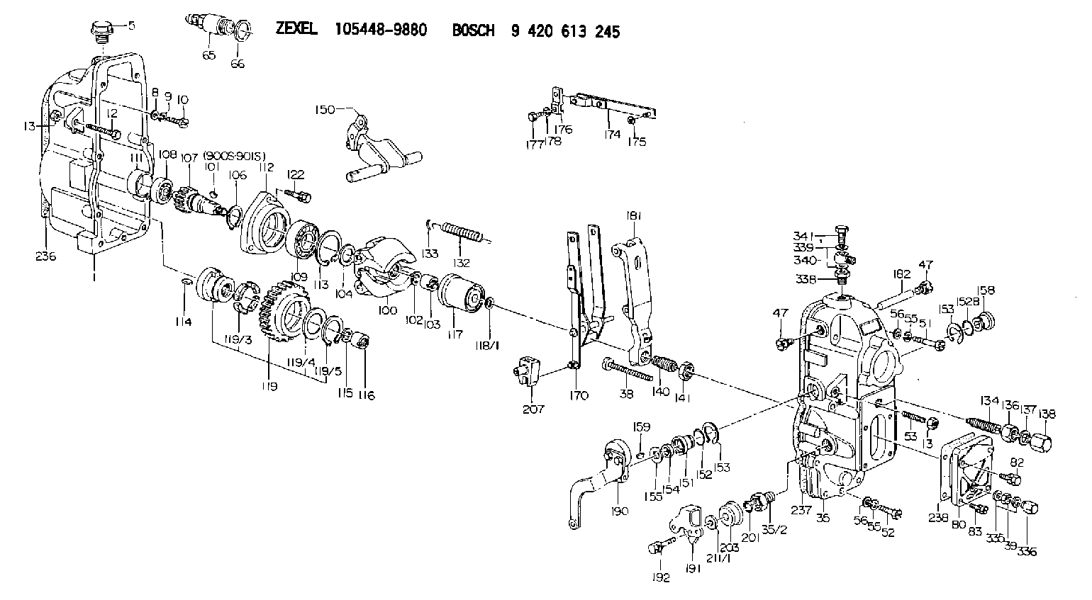
| 1. | [1] | 154002-2920 | GOVERNOR HOUSING |
| 5. | [1] | 154007-1600 | CAPSULE |
| 8. | [9] | 029300-6040 | PLAIN WASHER D11&6.4T1 |
| 9. | [9] | 029320-6010 | LOCKING WASHER |
| 10. | [9] | 029000-6490 | BLEEDER SCREW M6P1.0L23 |
| 12. | [1] | 154010-3900 | BLEEDER SCREW |
| 13. | [2] | 154011-0100 | HEXAGON NUT |
| 13. | [2] | 154011-0100 | HEXAGON NUT |
| 35. | [1] | 154520-7520 | GOVERNOR COVER |
| 35/2. | [1] | 154321-0200 | BUSHING |
| 38. | [1] | 154031-3000 | FLAT-HEAD SCREW |
| 39. | [1] | 013020-6040 | UNION NUT M6P1H5 |
| 47. | [2] | 154036-0300 | CAPSULE |
| 47. | [2] | 154036-0300 | CAPSULE |
| 51. | [4] | 029000-6470 | BLEEDER SCREW |
| 52. | [5] | 029000-6480 | BLEEDER SCREW M6P1.0L35 |
| 53. | [1] | 154010-0100 | FLAT-HEAD SCREW |
| 55. | [9] | 029320-6010 | LOCKING WASHER |
| 55. | [9] | 029320-6010 | LOCKING WASHER |
| 56. | [9] | 029300-6040 | PLAIN WASHER D11&6.4T1 |
| 56. | [9] | 029300-6040 | PLAIN WASHER D11&6.4T1 |
| 65. | [1] | 153020-3920 | STOPPING DEVICE |
| 66. | [1] | 029332-0050 | GASKET |
| 80. | [1] | 154063-0900 | COVER |
| 82. | [2] | 029020-6210 | BLEEDER SCREW |
| 83. | [2] | 029020-6210 | BLEEDER SCREW |
| 100. | [1] | 154100-9720 | FLYWEIGHT ASSEMBLY |
| 101. | [1] | 025803-1310 | WOODRUFF KEY |
| 102. | [1] | 029321-2020 | LOCKING WASHER |
| 103. | [1] | 029231-2030 | UNION NUT |
| 104. | [1] | 154120-0100 | PLAIN WASHER |
| 106. | [1] | 029602-0020 | LOCKING WASHER |
| 107. | [1] | 154121-0400 | TOOTHED GEAR |
| 108. | [1] | 016610-2640 | BEARING PLATE |
| 109. | [1] | 028102-0010 | BEARING PLATE |
| 111. | [1] | 154134-0000 | SPACER BUSHING |
| 112. | [1] | 154122-0300 | COVER |
| 113. | [1] | 029614-7020 | LOCKING WASHER |
| 114. | [1] | 025803-1610 | WOODRUFF KEY |
| 115. | [1] | 029321-2020 | LOCKING WASHER |
| 116. | [1] | 029231-2030 | UNION NUT |
| 117. | [1] | 154123-1920 | SLIDING PIECE |
| 118/1. | [0] | 029311-0010 | SHIM D14&10.1T0.2 |
| 118/1. | [0] | 029311-0180 | SHIM D14&10.1T0.3 |
| 118/1. | [0] | 029311-0190 | SHIM D14&10.1T0.40 |
| 118/1. | [0] | 029311-0210 | SHIM D14&10.1T1 |
| 118/1. | [0] | 139410-0000 | SHIM D14.0&10.1T0.5 |
| 118/1. | [0] | 139410-0100 | SHIM D14.0&10.1T1.5 |
| 118/1. | [0] | 139410-3000 | SHIM D14&10.1T2.0 |
| 118/1. | [0] | 139410-3100 | SHIM D14&10.1T3.0 |
| 118/1. | [0] | 139410-3200 | SHIM D14&10.1T4.0 |
| 119. | [1] | 154130-3020 | TOOTHED GEAR |
| 119/3. | [4] | 153251-0600 | DAMPER |
| 119/4. | [1] | 139329-0000 | PLAIN WASHER |
| 119/5. | [1] | 016020-2810 | LOCKING WASHER |
| 122. | [3] | 020106-2840 | BLEEDER SCREW |
| 132. | [1] | 154154-2900 | COILED SPRING |
| 133. | [2] | 154156-0100 | TUBE |
| 134. | [1] | 154158-0620 | HEADLESS SCREW |
| 136. | [1] | 029201-2290 | UNION NUT |
| 137. | [2] | 026512-1640 | GASKET D15.9&12.2T1 |
| 138. | [1] | 154159-1200 | CAP NUT |
| 140. | [1] | 154185-3120 | HEADLESS SCREW |
| 141. | [1] | 029201-6010 | UNION NUT |
| 150. | [1] | 154200-4520 | SWIVELLING LEVER |
| 151. | [1] | 154204-4100 | BUSHING |
| 152. | [1] | 139718-0000 | O-RING |
| 152B. | [1] | 029631-6110 | O-RING |
| 153. | [2] | 016010-1640 | LOCKING WASHER |
| 153. | [2] | 016010-1640 | LOCKING WASHER |
| 154. | [1] | 029621-1070 | PACKING RING |
| 155. | [1] | 029311-1010 | SHIM |
| 158. | [1] | 154204-2200 | BUSHING |
| 159. | [1] | 025803-1310 | WOODRUFF KEY |
| 170. | [1] | 154211-5220 | FORK LEVER |
| 174. | [1] | 154230-1820 | STRAP |
| 175. | [1] | 016010-0540 | LOCKING WASHER |
| 176. | [1] | 154232-0500 | CONNECTOR |
| 177. | [1] | 154316-2300 | BLEEDER SCREW |
| 178. | [1] | 029320-6010 | LOCKING WASHER |
| 181. | [1] | 154236-5821 | TENSIONING LEVER |
| 182. | [1] | 154237-0200 | BEARING PIN |
| 190. | [1] | 154347-4423 | CONTROL LEVER |
| 191. | [1] | 154365-4300 | CONTROL LEVER |
| 192. | [1] | 020006-2070 | BLEEDER SCREW M6P1L20 7T |
| 201. | [1] | 029630-9160 | O-RING |
| 203. | [1] | 154322-0100 | CAP |
| 207. | [1] | 154326-5020 | CONTROL LEVER |
| 211/1. | [0] | 029311-0520 | SHIM D20.8&10.3T0.2 |
| 211/1. | [0] | 029311-0530 | SHIM D20.8&10.3T0.25 |
| 211/1. | [0] | 029311-0540 | SHIM D20.8&10.3T0.3 |
| 211/1. | [0] | 029311-0550 | SHIM D20.8&10.3T0.35 |
| 211/1. | [0] | 029311-0560 | SHIM D20.8&10.3T0.4 |
| 211/1. | [0] | 029311-0570 | SHIM D20.8&10.3T0.5 |
| 236. | [1] | 154390-2900 | GASKET |
| 237. | [1] | 154390-3100 | GASKET |
| 238. | [1] | 154390-3500 | GASKET |
| 335. | [2] | 026506-1040 | GASKET D9.9&6.2T1 |
| 336. | [1] | 154035-1600 | CAP NUT |
| 338. | [1] | 131002-3800 | ADAPTOR |
| 339. | [2] | 029341-2140 | GASKET |
| 340. | [1] | 154373-1800 | INLET UNION |
| 341. | [1] | 154373-1700 | EYE BOLT |
| 900S. | [1] | 025803-1310 | WOODRUFF KEY |
| 901S. | [1] | 025803-1610 | WOODRUFF KEY |
Include in #1:
106692-9060
as GOVERNOR
Cross reference number
Zexel num
Bosch num
Firm num
Name
Information:
Illustration 6 g06375966
Current hose routing
(E) 3U-2752 Clip
Illustration 7 g06375968
(D3) 32.31 mm (1.272 inch)
(D4) 80.00 mm (3.150 inch)
(1) 178-7023 Boss
Illustration 8 g06375967
New hose routing
(1) 178-7023 Boss
(2) 420-5299 Clip
Remove clip (E) and install boss (1) per the dimensions and secure the hose using two double clips (2), as shown in Illustration 6, Illustration 7, and Illustration 8.Changes to CEM Line Routing for 730C2, 730C2 EJ, 730, and 735 Articulated Trucks
Illustration 9 g06376002
Current hose routing
(F) 421-9627 Bracket As
(G) 3U-2752 Clip
(H) 7K-1181 Cable Strap
Remove bracket assembly (F), clips (G), strap cable (H), and other mounting hardware, as shown in Illustration 9.
Illustration 10 g06376255
New hose routing
(2) 420-5299 Clip
Install two double clips (2) as shown in Illustration 10.Note: The hose routing simplifies the installation and provides additional clearance to the oil gallery on the right-hand side of the machine.Changes to DEF cooling Lines Routing (To/From Tank) for all High Regulated Countries (HRC) Machines
Illustration 11 g06376256
Current hose routing
(J) 312-0288 Clamp
Illustration 12 g06376257
New hose routing
(3) 520-7003 ClampRemove old clamps (J) and replace with the new clamps (3), as shown in Illustration 11 and Illustration 12.Changes to DEF Cooling Lines Routing (To Pump- Both ends) for all HRC Machines
Illustration 13 g06376263
Current clamp
(J) 312-0288 Clamp
Illustration 14 g06376264
New clamp
(3) 520-7003 Clamp
Illustration 15 g06376266
Current clamp
(J) 312-0288 Clamp
Illustration 16 g06376267
New clamp
(3) 520-7003 ClampRemove old clamps (J) and replace with the new clamps (3), as shown in Illustration 13, Illustration 14, Illustration 15, and Illustration 16.Changes to DEF Cooling Lines (From Pump- Both ends) Routing for all HRC Machines
Illustration 17 g06376285
Current clamp
(K) 433-0933 Clamp
Illustration 18 g06376288
New clamp
(4) 520-7002 ClampRemove existing clamps (K) and replace with the new clamps (4), as shown in Illustration 17 and Illustration 18.