Information governor
BOSCH
F 019 Z1F 020
f019z1f020
ZEXEL
105448-9432
1054489432

Rating:
Scheme ###:
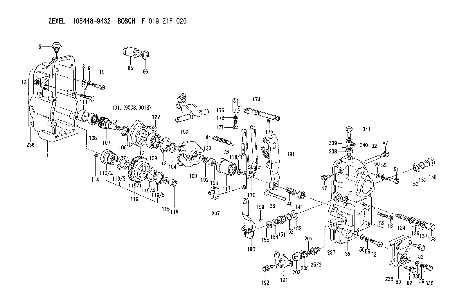
| 1. | [1] | 154002-2920 | GOVERNOR HOUSING |
| 5. | [1] | 154007-1600 | CAPSULE |
| 8. | [9] | 029300-6040 | PLAIN WASHER D11&6.4T1 |
| 9. | [9] | 029320-6010 | LOCKING WASHER |
| 10. | [9] | 029000-6490 | BLEEDER SCREW M6P1.0L23 |
| 12. | [1] | 154010-3900 | BLEEDER SCREW |
| 13. | [2] | 154011-0100 | HEXAGON NUT |
| 13. | [2] | 154011-0100 | HEXAGON NUT |
| 35. | [1] | 154520-2420 | GOVERNOR COVER |
| 35/2. | [1] | 154321-0200 | BUSHING |
| 38. | [1] | 154031-3000 | FLAT-HEAD SCREW |
| 39. | [1] | 013020-6040 | UNION NUT M6P1H5 |
| 47. | [2] | 154036-0300 | CAPSULE |
| 47. | [2] | 154036-0300 | CAPSULE |
| 51. | [4] | 029000-6470 | BLEEDER SCREW |
| 52. | [5] | 029000-6480 | BLEEDER SCREW M6P1.0L35 |
| 53. | [1] | 154010-0200 | FLAT-HEAD SCREW |
| 55. | [9] | 029320-6010 | LOCKING WASHER |
| 55. | [9] | 029320-6010 | LOCKING WASHER |
| 56. | [9] | 029300-6040 | PLAIN WASHER D11&6.4T1 |
| 56. | [9] | 029300-6040 | PLAIN WASHER D11&6.4T1 |
| 65. | [1] | 154050-3900 | CAP |
| 66. | [1] | 029332-0050 | GASKET |
| 80. | [1] | 154063-0900 | COVER |
| 82. | [2] | 029020-6210 | BLEEDER SCREW |
| 83. | [2] | 029020-6210 | BLEEDER SCREW |
| 100. | [1] | 154100-9720 | FLYWEIGHT ASSEMBLY |
| 101. | [1] | 025803-1610 | WOODRUFF KEY |
| 102. | [1] | 029321-2020 | LOCKING WASHER |
| 103. | [1] | 029231-2030 | UNION NUT |
| 104. | [1] | 154120-0100 | PLAIN WASHER |
| 106. | [1] | 029602-0020 | LOCKING WASHER |
| 107. | [1] | 154121-0500 | TOOTHED GEAR |
| 108. | [1] | 016610-2640 | BEARING PLATE |
| 109. | [1] | 028102-0010 | BEARING PLATE |
| 111. | [1] | 154134-0000 | SPACER BUSHING |
| 112. | [1] | 154122-0300 | COVER |
| 113. | [1] | 029614-7020 | LOCKING WASHER |
| 114. | [1] | 025803-1310 | WOODRUFF KEY |
| 115. | [1] | 029321-2020 | LOCKING WASHER |
| 116. | [1] | 029231-2030 | UNION NUT |
| 117. | [1] | 154123-1920 | SLIDING PIECE |
| 118/1. | [0] | 029311-0010 | SHIM D14&10.1T0.2 |
| 118/1. | [0] | 029311-0180 | SHIM D14&10.1T0.3 |
| 118/1. | [0] | 029311-0190 | SHIM D14&10.1T0.40 |
| 118/1. | [0] | 029311-0210 | SHIM D14&10.1T1 |
| 118/1. | [0] | 139410-0000 | SHIM D14.0&10.1T0.5 |
| 118/1. | [0] | 139410-0100 | SHIM D14.0&10.1T1.5 |
| 118/1. | [0] | 139410-3000 | SHIM D14&10.1T2.0 |
| 118/1. | [0] | 139410-3100 | SHIM D14&10.1T3.0 |
| 118/1. | [0] | 139410-3200 | SHIM D14&10.1T4.0 |
| 119. | [1] | 154130-1820 | TOOTHED GEAR |
| 119/1. | [1] | 154130-0510 | TOOTHED GEAR |
| 119/2. | [1] | 154132-0320 | HOLDER |
| 119/3. | [4] | 153251-0100 | DAMPER |
| 119/4. | [1] | 139329-0000 | PLAIN WASHER |
| 119/5. | [1] | 016020-2810 | LOCKING WASHER |
| 122. | [3] | 020106-2840 | BLEEDER SCREW |
| 132. | [1] | 154154-0900 | COILED SPRING |
| 133. | [2] | 154156-0100 | TUBE |
| 134. | [1] | 154158-0620 | HEADLESS SCREW |
| 136. | [1] | 029201-2290 | UNION NUT |
| 137. | [2] | 026512-1640 | GASKET D15.9&12.2T1 |
| 138. | [1] | 154159-1200 | CAP NUT |
| 140. | [1] | 154170-0220 | HEADLESS SCREW |
| 141. | [1] | 029201-6010 | UNION NUT |
| 150. | [1] | 154200-4520 | SWIVELLING LEVER |
| 151. | [1] | 154204-2100 | BUSHING |
| 152. | [2] | 139716-0100 | O-RING |
| 152. | [2] | 139716-0100 | O-RING |
| 153. | [2] | 016010-1640 | LOCKING WASHER |
| 153. | [2] | 016010-1640 | LOCKING WASHER |
| 154. | [1] | 139611-0200 | PACKING RING |
| 155. | [1] | 029311-1010 | SHIM |
| 158. | [1] | 154204-2200 | BUSHING |
| 159. | [1] | 025803-1310 | WOODRUFF KEY |
| 170. | [1] | 154211-5220 | FORK LEVER |
| 174. | [1] | 154230-1820 | STRAP |
| 175. | [1] | 016010-0540 | LOCKING WASHER |
| 176. | [1] | 154232-0500 | CONNECTOR |
| 177. | [1] | 154316-2300 | BLEEDER SCREW |
| 178. | [1] | 029320-6010 | LOCKING WASHER |
| 181. | [1] | 154236-5821 | TENSIONING LEVER |
| 182. | [1] | 154237-0200 | BEARING PIN |
| 190. | [1] | 154345-1520 | CONTROL LEVER |
| 191. | [1] | 154304-9420 | CONTROL LEVER |
| 192. | [1] | 020006-2040 | BLEEDER SCREW M6P1L20 4T |
| 201. | [1] | 139710-0400 | O-RING |
| 203. | [1] | 154322-0100 | CAP |
| 207. | [1] | 154326-5020 | CONTROL LEVER |
| 208. | [1] | 154327-7600 | COILED SPRING |
| 236. | [1] | 154390-2900 | GASKET |
| 237. | [1] | 154390-3100 | GASKET |
| 238. | [1] | 154390-3500 | GASKET |
| 335. | [2] | 026506-1040 | GASKET D9.9&6.2T1 |
| 336. | [1] | 154035-1600 | CAP NUT |
| 338. | [1] | 131002-3800 | ADAPTOR |
| 339. | [2] | 029341-2140 | GASKET |
| 340. | [1] | 029711-2350 | INLET UNION |
| 341. | [1] | 029731-2240 | EYE BOLT |
| 900S. | [1] | 025803-1310 | WOODRUFF KEY |
| 901S. | [1] | 025803-1610 | WOODRUFF KEY |
Cross reference number
Zexel num
Bosch num
Firm num
Name
105448-9432
GOVERNOR
K 14JC MECHANICAL GOVERNOR GOV RSUV(D) GOV
K 14JC MECHANICAL GOVERNOR GOV RSUV(D) GOV
Information:
Machine Preparation
Prepare the machine for maintenance.Refer to Operation and Maintenance Manual, SEBU8491, "Prepare the Machine for Maintenance".Removal Procedure
Illustration 2 g06215589
(A) 383-2040 Guard
(B) 8T-4195 Bolt
(C) 8T-4121 Hard Washer
(D) 384-0966 Insert
Remove and save the DEF guard (A), three bolts (B), three hard washers (C), and three inserts (D).
Illustration 3 g06217988
(C) 8T-4121 Hard Washer
(E) 368-4513 Side Plate
(F) 365-2227 Hose As
(G) 8T-4136 Bolt
(H) 1S-0994 Clip
(J) 8T-4137 Bolt
(K) 1S-1015 Clip
(L) 7K-1181 Cable Strap
Illustration 4 g06217851
(E) 368-4513 Side Plate
Illustration 5 g06219874
View of Area M
(C) 8T-4121 Hard Washer
(H) 1S-0994 Clip
(N) 399-3078 Machine Software Gp
(P) 434-1305 Insulation
(R) 326-4516 Cable Tie
(S) 8T-4195 Bolt
(T) 7X-7729 Washer
(U) 8T-4133 Nut
Remove six hard washers (C), two bolts (G), five clips (H), two bolts (J), clip (K), four cable straps (L), five cable ties (R), protective insulation (P), two bolts (S), two washers (T), and two nuts (U) from the hose assembly (F). Discard five clips (H), clip (K), five cable ties (R). Retain the rest of the parts.
Remove and discard hose assembly (F) from DEF tank and DEF Injector Mounting Gp (N). Refer to Illustration 3 and Illustration 5.Installation Procedure
Illustration 6 g06215872
(C) 8T-4121 Hard Washer
(G) 8T-4136 Bolt
(J) 8T-4137 Bolt
(1) 471-4171 Hose As
(2) 1S-0994 Clip
(3) 7K-1181 Cable Strap
(4) 1S-1015 Clip
Illustration 7 g06219875
View of Area M
(C) 8T-4121 Hard Washer
(N) 399-6078 DEF Injector & Mounting Gp
(P) 434-1305 Insulation
(S) 8T-4195 Bolt
(T) 7X-7729 Washer
(U) 8T-4133 Nut
(1) 471-4171 Hose As
(2) 1S-0994 Clip
(5) 326-4516 Cable Tie
Install new hose assembly (1) to the DEF tank and DEF injector mounting group (N). Secure hose assembly (1) using five clips (2), four cable straps (3), clip (4), six hard washers (C), two bolts (G), two bolts (J), two bolts (S), two washers (T), and two nuts (U) that were saved in Step 2 of Section "Removal Procedure". Refer to Illustration 6 and Illustration 7.
Secure protective insulation (P) that was saved in Step 2 of Section "Removal Procedure" to hose assembly (1) using five cable ties (5). Refer to Illustration 7.
Illustration 8 g06215593
(A) 383-2040 Guard
(V) Template
Illustration 9 g06215595
(X) 94.4 mm (3.72 inch)
(Y) 225 mm (8.9 inch)
Use Illustration 9 as a template and position the template onto guard (A), aligning to the edges. Trim the guard (A) according to the template. Refer to Illustration 8.Note: Lay the template flat on the guard. The trimmed area of the guard (A) is the curved area. The square cutout on the template is not to be cut, the square corner allows the template to lay flatter on the guard.
Illustration 10 g06215889
(A) 383-2040 Guard
(E) 368-4513 Side Plate
(1) 471-4171 Hose As
Install the modified DEF guard (A) using the hardware that was saved in Step 1 of Section "Removal Procedure".Note: Ensure adequate clearance has been obtained.
Return machine to service.