Information governor
BOSCH
9 420 614 996
9420614996
ZEXEL
105447-5840
1054475840

Rating:
Scheme ###:
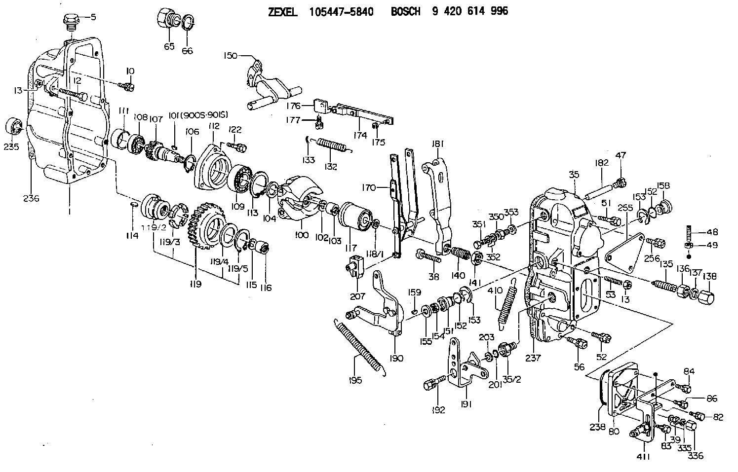
| 1. | [1] | 154002-4020 | GOVERNOR HOUSING |
| 5. | [1] | 154007-1600 | CAPSULE |
| 10. | [8] | 139006-4100 | BLEEDER SCREW |
| 12. | [1] | 154034-0800 | BLEEDER SCREW |
| 13. | [2] | 154011-0100 | HEXAGON NUT |
| 13. | [2] | 154011-0100 | HEXAGON NUT |
| 35. | [1] | 154023-4421 | GOVERNOR COVER |
| 35/2. | [1] | 154321-0400 | BUSHING |
| 38. | [1] | 154031-3000 | FLAT-HEAD SCREW |
| 39. | [1] | 139206-0600 | UNION NUT |
| 47. | [1] | 154036-0300 | CAPSULE |
| 48. | [1] | 154037-2300 | FLAT-HEAD SCREW |
| 49. | [1] | 154038-0200 | HEXAGON NUT |
| 51. | [3] | 020106-5040 | BLEEDER SCREW |
| 52. | [3] | 020106-2840 | BLEEDER SCREW |
| 53. | [1] | 154034-0800 | BLEEDER SCREW |
| 56. | [1] | 029010-6080 | BLEEDER SCREW M6P1.0L50 |
| 65. | [1] | 155404-1700 | CAP |
| 66. | [1] | 026524-3040 | GASKET |
| 80. | [1] | 154063-8200 | COVER |
| 82. | [1] | 029020-6210 | BLEEDER SCREW |
| 83. | [1] | 029020-6260 | BLEEDER SCREW |
| 84. | [1] | 029020-6260 | BLEEDER SCREW |
| 86. | [1] | 029020-6260 | BLEEDER SCREW |
| 100. | [1] | 154100-6320 | FLYWEIGHT ASSEMBLY |
| 101. | [1] | 025803-1610 | WOODRUFF KEY |
| 102. | [1] | 029321-2020 | LOCKING WASHER |
| 103. | [1] | 029231-2030 | UNION NUT |
| 104. | [1] | 154120-0100 | PLAIN WASHER |
| 106. | [1] | 029602-0020 | LOCKING WASHER |
| 107. | [1] | 154121-0500 | TOOTHED GEAR |
| 108. | [1] | 016610-2640 | BEARING PLATE |
| 109. | [1] | 028102-0010 | BEARING PLATE |
| 111. | [1] | 154134-0000 | SPACER BUSHING |
| 112. | [1] | 154122-0100 | COVER |
| 113. | [1] | 029614-7020 | LOCKING WASHER |
| 114. | [1] | 025803-1310 | WOODRUFF KEY |
| 115. | [1] | 029321-2020 | LOCKING WASHER |
| 116. | [1] | 029231-2030 | UNION NUT |
| 117. | [1] | 154123-1920 | SLIDING PIECE |
| 118/1. | [0] | 029311-0010 | SHIM D14&10.1T0.2 |
| 118/1. | [0] | 029311-0180 | SHIM D14&10.1T0.3 |
| 118/1. | [0] | 029311-0190 | SHIM D14&10.1T0.40 |
| 118/1. | [0] | 029311-0210 | SHIM D14&10.1T1 |
| 118/1. | [0] | 139410-0000 | SHIM D14.0&10.1T0.5 |
| 118/1. | [0] | 139410-0100 | SHIM D14.0&10.1T1.5 |
| 118/1. | [0] | 139410-3000 | SHIM D14&10.1T2.0 |
| 118/1. | [0] | 139410-3100 | SHIM D14&10.1T3.0 |
| 118/1. | [0] | 139410-3200 | SHIM D14&10.1T4.0 |
| 119. | [1] | 154130-1820 | TOOTHED GEAR |
| 119/2. | [1] | 154132-0320 | HOLDER |
| 119/3. | [4] | 153251-0100 | DAMPER |
| 119/4. | [1] | 139329-0000 | PLAIN WASHER |
| 119/5. | [1] | 016020-2810 | LOCKING WASHER |
| 122. | [3] | 020106-2840 | BLEEDER SCREW |
| 132. | [1] | 154154-0900 | COILED SPRING |
| 133. | [2] | 154156-0100 | TUBE |
| 135. | [1] | 154158-4320 | HEADLESS SCREW |
| 136. | [1] | 029201-2290 | UNION NUT |
| 137. | [2] | 026512-1540 | GASKET D15.4&12.2T1.50 |
| 138. | [1] | 154159-1200 | CAP NUT |
| 140. | [1] | 154176-3620 | HEADLESS SCREW |
| 141. | [1] | 029201-6010 | UNION NUT |
| 150. | [1] | 154200-4520 | SWIVELLING LEVER |
| 151. | [1] | 154204-2100 | BUSHING |
| 152. | [2] | 139716-0100 | O-RING |
| 152. | [2] | 139716-0100 | O-RING |
| 153. | [2] | 016010-1640 | LOCKING WASHER |
| 153. | [2] | 016010-1640 | LOCKING WASHER |
| 154. | [1] | 139611-0200 | PACKING RING |
| 155. | [1] | 029311-1010 | SHIM |
| 158. | [1] | 154204-2200 | BUSHING |
| 159. | [1] | 025803-1310 | WOODRUFF KEY |
| 170. | [1] | 154211-7620 | FORK LEVER |
| 174. | [1] | 154230-0220 | STRAP |
| 175. | [1] | 016010-0540 | LOCKING WASHER |
| 176. | [1] | 154232-0400 | CONNECTOR |
| 177. | [2] | 029050-5040 | FLAT-HEAD SCREW M5P0.8L9 |
| 181. | [1] | 154236-8620 | TENSIONING LEVER |
| 182. | [1] | 154237-1500 | BEARING PIN |
| 190. | [1] | 154349-7720 | CONTROL LEVER |
| 191. | [1] | 154381-0120 | CONTROL LEVER |
| 192. | [1] | 020006-3040 | BLEEDER SCREW |
| 195. | [1] | 154314-1800 | COILED SPRING |
| 201. | [1] | 139710-0500 | O-RING |
| 203. | [0] | 029311-0220 | SHIM D18&10.3T0.2 |
| 203B. | [0] | 029311-0230 | SHIM D18&10.3T0.5 |
| 207. | [1] | 154326-8720 | LEVER GROUP |
| 235. | [1] | 029621-7010 | PACKING RING |
| 236. | [1] | 154371-5600 | GASKET |
| 237. | [1] | 154371-3500 | GASKET |
| 238. | [1] | 154390-3500 | GASKET |
| 255. | [1] | 154373-5820 | BRACKET |
| 256. | [2] | 020006-1240 | BLEEDER SCREW M6P1L12 4T |
| 335. | [2] | 026506-1040 | GASKET D9.9&6.2T1 |
| 336. | [1] | 154035-1600 | CAP NUT |
| 350. | [1] | 154036-1600 | ADAPTOR |
| 351. | [1] | 139806-0000 | EYE BOLT |
| 352. | [2] | 029340-6120 | GASKET |
| 353. | [1] | 026510-1340 | GASKET D13.4&10.2T1 |
| 410. | [1] | 154332-3100 | COILED SPRING |
| 411. | [1] | 154373-3720 | BRACKET |
| 900S. | [1] | 025803-1310 | WOODRUFF KEY |
| 901S. | [1] | 025803-1610 | WOODRUFF KEY |
Cross reference number
Zexel num
Bosch num
Firm num
Name
Information:
Indicator Readings
If, the indicator reading a positive (+), the tip of the indicator moved into the indicator and minus (-) means that the tip of the indicator moved out of the dial indicator.When comparing two positive (+) indicator readings, the larger numerical reading is more than the smaller numerical reading. However, when comparing two minus (-) indicator readings, the larger numerical reading is less than the smaller numerical reading. In both cases, the indicator reading becomes less as the tip of the indicator moves out of the dial indicator.The Total Indicator Reading (TIR) is the total amount of movement of the indicator needle. The TIR is always a positive value even though one or both of the readings are negative. For example: If the indicator reading varied from -10 to +5, the TIR was 15. If the indicator reading is varied from -5 to - 15, the TIR was 10.Laser Tool Alignment Procedure
Note: Refer to the laser alignment tool user manual instructions for additional information regarding operation of the tool.To do laser tool alignment, perform the following steps:
Mount the transducer to the outer coupling element.
Attach the reflector to the generator hub.
Enter the required dimensions into the laser alignment tool. Examples of possible dimensions required include the following:
Transducer to reflector
Transducer to coupling centerline
Coupling diameter
Rotations Per Minute (RPM)
Transducer to front feet
Front feet to rear feet
Turn the laser ON, adjust the laser beam to the center of the reflector dust cap. Once the laser beam is centered, remove the dust cap.
Rotate the drive line one complete revolution.
Record the results displayed on the laser alignment tool. Compare the readings to the acceptable values listed in the "Generator Set Alignment Data Sheet".
Adjust the generator as needed to obtain the correct alignment. Shims may be installed or removed to achieve the correct vertical alignment. Use the horizontal adjustment screws to make horizontal adjustments.
Once the alignment is within the specifications, torque the generator mounting bolts to the proper specifications.
Perform a soft foot check. Refer to "Soft Foot Check Procedure".Soft Foot Check Procedure
Note: The soft foot check can be completed with the laser alignment tool if the tool has this function.
Ensure that all jacking screws are loose
Mount a dial indicator from the base assembly to the top of the generator mounting foot to be measured.
Preload the dial indicator to a minimum of one revolution or 2 mm (0.08 inch). Once the correct preload is set, zero the dial indicator.
Loosen the mounting bolt at the location that is being measured. Measure and record the vertical deflection of the generator mounting foot at this location as close to the mounting bolt as possible. Only loosen one bolt at a time.
The maximum deflection of the mounting foot is 0.076 mm (0.003 inch). If the indicator reading is greater than this amount, add shims to eliminate the soft foot condition. Torque the mounting bolt before moving to the next mounting foot to be measured for soft foot.
Repeat the procedure on the remaining generator mounting feet.
Perform the final torque of the