Information governor
BOSCH
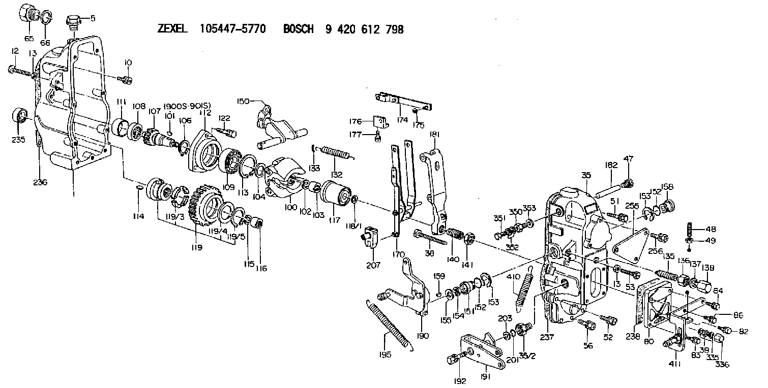
9 420 612 798
9420612798
ZEXEL
105447-5770
1054475770
Rating:
Scheme ###:
| 1. | [1] | 154002-4020 | GOVERNOR HOUSING |
| 5. | [1] | 154007-1600 | CAPSULE |
| 10. | [8] | 139006-4100 | BLEEDER SCREW |
| 12. | [1] | 154034-0800 | BLEEDER SCREW |
| 13. | [2] | 154011-0100 | HEXAGON NUT |
| 13. | [2] | 154011-0100 | HEXAGON NUT |
| 35. | [1] | 154023-4421 | GOVERNOR COVER |
| 35/2. | [1] | 154321-0400 | BUSHING |
| 38. | [1] | 154031-3000 | FLAT-HEAD SCREW |
| 39. | [1] | 139206-0600 | UNION NUT |
| 47. | [1] | 154036-0300 | CAPSULE |
| 48. | [1] | 154037-2300 | FLAT-HEAD SCREW |
| 49. | [1] | 154038-0200 | HEXAGON NUT |
| 51. | [3] | 020106-5040 | BLEEDER SCREW |
| 52. | [3] | 020106-2840 | BLEEDER SCREW |
| 53. | [1] | 154034-0800 | BLEEDER SCREW |
| 56. | [1] | 029010-6080 | BLEEDER SCREW M6P1.0L50 |
| 65. | [1] | 155404-1700 | CAP |
| 66. | [1] | 026524-3040 | GASKET |
| 80. | [1] | 154063-8200 | COVER |
| 82. | [1] | 029020-6210 | BLEEDER SCREW |
| 83. | [1] | 029020-6260 | BLEEDER SCREW |
| 84. | [1] | 029020-6260 | BLEEDER SCREW |
| 86. | [1] | 029020-6260 | BLEEDER SCREW |
| 100. | [1] | 154100-6320 | FLYWEIGHT ASSEMBLY |
| 101. | [1] | 025803-1310 | WOODRUFF KEY |
| 102. | [1] | 029321-2020 | LOCKING WASHER |
| 103. | [1] | 029231-2030 | UNION NUT |
| 104. | [1] | 154120-0100 | PLAIN WASHER |
| 106. | [1] | 029602-0020 | LOCKING WASHER |
| 107. | [1] | 154121-0500 | TOOTHED GEAR |
| 108. | [1] | 016610-2640 | BEARING PLATE |
| 109. | [1] | 028102-0010 | BEARING PLATE |
| 111. | [1] | 154134-0000 | SPACER BUSHING |
| 112. | [1] | 154122-0100 | COVER |
| 113. | [1] | 029614-7020 | LOCKING WASHER |
| 114. | [1] | 025803-1610 | WOODRUFF KEY |
| 115. | [1] | 029321-2020 | LOCKING WASHER |
| 116. | [1] | 029231-2030 | UNION NUT |
| 117. | [1] | 154123-1920 | SLIDING PIECE |
| 118/1. | [0] | 029311-0010 | SHIM D14&10.1T0.2 |
| 118/1. | [0] | 029311-0180 | SHIM D14&10.1T0.3 |
| 118/1. | [0] | 029311-0190 | SHIM D14&10.1T0.40 |
| 118/1. | [0] | 029311-0210 | SHIM D14&10.1T1 |
| 118/1. | [0] | 139410-0000 | SHIM D14.0&10.1T0.5 |
| 118/1. | [0] | 139410-0100 | SHIM D14.0&10.1T1.5 |
| 118/1. | [0] | 139410-3000 | SHIM D14&10.1T2.0 |
| 118/1. | [0] | 139410-3100 | SHIM D14&10.1T3.0 |
| 118/1. | [0] | 139410-3200 | SHIM D14&10.1T4.0 |
| 119. | [1] | 154130-1820 | TOOTHED GEAR |
| 119/3. | [4] | 153251-0100 | DAMPER |
| 119/4. | [1] | 139329-0000 | PLAIN WASHER |
| 119/5. | [1] | 016020-2810 | LOCKING WASHER |
| 122. | [3] | 020106-2840 | BLEEDER SCREW |
| 132. | [1] | 154154-0900 | COILED SPRING |
| 133. | [2] | 154156-0100 | TUBE |
| 135. | [1] | 154157-6020 | HEADLESS SCREW |
| 136. | [1] | 029201-2030 | UNION NUT M12P1.0H4 |
| 137. | [2] | 026512-1540 | GASKET D15.4&12.2T1.50 |
| 138. | [1] | 154159-1200 | CAP NUT |
| 140. | [1] | 154176-3620 | HEADLESS SCREW |
| 141. | [1] | 029201-6010 | UNION NUT |
| 150. | [1] | 154200-4520 | SWIVELLING LEVER |
| 151. | [1] | 154204-2100 | BUSHING |
| 152. | [2] | 139716-0100 | O-RING |
| 152. | [2] | 139716-0100 | O-RING |
| 153. | [2] | 016010-1640 | LOCKING WASHER |
| 153. | [2] | 016010-1640 | LOCKING WASHER |
| 154. | [1] | 139611-0200 | PACKING RING |
| 155. | [1] | 029311-1010 | SHIM |
| 158. | [1] | 154204-2200 | BUSHING |
| 159. | [1] | 025803-1310 | WOODRUFF KEY |
| 170. | [1] | 154211-7620 | FORK LEVER |
| 174. | [1] | 154230-0220 | STRAP |
| 175. | [1] | 016010-0540 | LOCKING WASHER |
| 176. | [1] | 154232-0400 | CONNECTOR |
| 177. | [2] | 029050-5040 | FLAT-HEAD SCREW M5P0.8L9 |
| 181. | [1] | 154236-8620 | TENSIONING LEVER |
| 182. | [1] | 154237-1500 | BEARING PIN |
| 190. | [1] | 154349-7720 | CONTROL LEVER |
| 191. | [1] | 154382-1520 | CONTROL LEVER |
| 192. | [1] | 020006-3040 | BLEEDER SCREW |
| 195. | [1] | 154314-1800 | COILED SPRING |
| 201. | [1] | 139710-0500 | O-RING |
| 203. | [0] | 029311-0220 | SHIM D18&10.3T0.2 |
| 203B. | [0] | 029311-0230 | SHIM D18&10.3T0.5 |
| 207. | [1] | 154326-5420 | CONTROL LEVER |
| 235. | [1] | 029621-7010 | PACKING RING |
| 236. | [1] | 154371-5600 | GASKET |
| 237. | [1] | 154371-3500 | GASKET |
| 238. | [1] | 154390-3500 | GASKET |
| 255. | [1] | 154373-5820 | BRACKET |
| 256. | [2] | 020006-1240 | BLEEDER SCREW M6P1L12 4T |
| 335. | [2] | 026506-1040 | GASKET D9.9&6.2T1 |
| 336. | [1] | 154035-1600 | CAP NUT |
| 350. | [1] | 154036-1600 | ADAPTOR |
| 351. | [1] | 139806-0000 | EYE BOLT |
| 352. | [2] | 029340-6120 | GASKET |
| 353. | [1] | 026510-1340 | GASKET D13.4&10.2T1 |
| 410. | [1] | 154332-3100 | COILED SPRING |
| 411. | [1] | 154373-3720 | BRACKET |
| 900S. | [1] | 025803-1310 | WOODRUFF KEY |
| 901S. | [1] | 025803-1610 | WOODRUFF KEY |
Include in #1:
106682-9040
as GOVERNOR
Cross reference number
Zexel num
Bosch num
Firm num
Name
Information:
API Degrees - Temperature Correction Chart for Diesel Fuel
Record the corrected API gravity from this chart.Table of Horsepower Correction Factors
Table 2
Corrected API
Gravity at 60° F Precombustion
Chamber Engines Direct Injection Engines (Use the correct full load RPM)
1800 2000 2200 2400 2600 2800 3000 3200
32.0
32.5
33.0
33.5
34.0 .984
.987
.990
.992
.995 .986
.988
.990
.992
.995 .986
.988
.990
.992
.995 .986
.988
.990
.992
.995 .986
.988
.990
.992
.995 .986
.988
.990
.992
.995 .986
.988
.990
.992
.995 .986
.988
.990
.992
.995 .986
.988
.990
.992
.995
34.5
35.0
35.5
36.0
36.5 .997
1.000
1.003
1.005
1.008 .998
1.000
1.003
1.007
1.013 .998
1.000
1.003
1.007
1.010 .998
1.000
1.004
1.007
1.011 .998
1.000
1.004
1.007
1.011 .998
1.000
1.004
1.007
1.011 .998
1.000
1.004
1.008
1.012 .998
1.000
1.004
1.008
1.012 .998
1.000
1.004
1.008
1.012
37.0
37.5
38.0
38.5
39.0 1.011
1.014
1.017
1.020
1.023 1.014
1.018
1.022
1.025
1.029 1.014
1.018
1.022
1.026
1.030 1.014
1.018
1.022
1.026
1.030 1.015
1.019
1.022
1.026
1.030 1.015
1.019
1.023
1.027
1.031 1.016
1.020
1.024
1.028
1.032 1.016
1.020
1.024
1.028
1.033 1.016
1.021
1.025
1.029
1.034
39.5
40.0
40.5
41.0
41.5 1.027
1.030
1.034
1.038
1.043 1.034
1.038
1.043
1.048
1.053 1.034
1.038
1.043
1.048
1.054 1.034
1.039
1.044
1.049
1.055 1.035
1.040
1.045
1.050
1.056 1.036
1.040
1.045
1.051
1.056 1.036
1.041
1.046
1.051
1.057 1.037
1.042
1.047
1.053
1.059 1.039
1.045
1.047
1.057
1.064
42.0
42.5
43.0
43.5
44.0 1.047
1.053
1.060
1.067
1.076 1.059
1.066
1.073
1.082
1.095 1.060
1.067
1.074
1.084
1.096 1.061
1.068
1.076
1.085
1.098 1.062
1.069
1.077
1.086
1.099 1.063
1.070
1.078
1.087
1.100 1.064
1.071
1.079
1.088
1.102 1.066
1.072
1.081
1.091
1.105 1.072
1.080
1.089
1.099
1.115 Use the above chart to find the horsepower correction factor.Calculating the Corrected Horsepower
Determine the rated full load horsepower from the Rack Setting Information Book.
Divide the rated horsepower by the horsepower correction factor for fuel density; the result is the corrected horsepower.Example:1674 - Truck Engine Serial No. 94B2551Rated Horsepower: 270 HorsepowerCalculations:
Table 3
1. Measured API gravity: 40.4' API at 50' (round to 40' API)
2. Corrected API gravity (see chart): 41' API at 60'F
3. Hpr correction factor (see chart): 1.038
4. Corrected Hp = Rated Hpr = 270 = 260 Hp
Correction Factor 1.038 (or 3.75% hp loss) Correcting for Fuel Density When Testing Engines on a Dynamometer
When engines are tested on a dynamometer which measures actual flywheel or drive train output, the observed horsepower is dependent on the fuel used. If the fuel being used is not 35° API at 60°F, then any dynamometer readings must be corrected to determine the output if 35° API fuel had been used. The same horsepower correction factor is used, but the formula is different:Corrected Horsepower = Observed Horsepower x Horsepower Correction FactorExample:1674 Truck Engine, Serial No. 9482551Rated (full load Horsepower: 270 Horsepower)Observed (dynamometer) Horsepower: 260 HorsepowerCalculations:
Measured API gravity: 39.6° API at 50°F (round to 40° API)
Corrected API Gravity (see chart): 41° API at 60°F
Horsepower Correction Factor (see chart): 1.038
Corrected Horsepower = Observed Horsepower x Horsepower Correction Factor 260 horsepower x 1.038 = 270 horsepower(Although the dynamometer indicated low horsepower, if the proper fuel had been used, the engine would be operating at rated output. The factory tolerance on rated engine output is 3%.)REFERENCE: For more information on dynamometer testing diesel engines, see Special Instruction Form GEG01024 .Diesel Fuel API Gravity to IbsJU.S. gallon or kg/liter Conversion Chart
The following chart may be used to convert the fuel API gravity to Ibs./U.S. gallon or kg/liter. These weights are for reference and are to be used when evaluating engine performance. Measurement of fuel flow rates can be converted