Information governor
BOSCH
F 01G 29N 0BJ
f01g29n0bj
ZEXEL
105447-2571
1054472571
Rating:
Scheme ###:
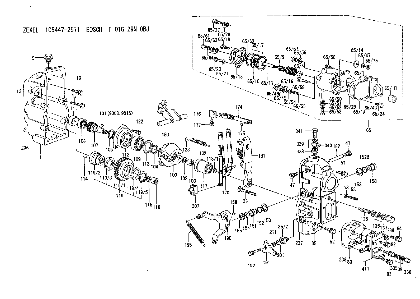
| 1. | [1] | 154002-4420 | GOVERNOR HOUSING |
| 5. | [1] | 154007-1600 | CAPSULE |
| 10. | [8] | 139006-4100 | BLEEDER SCREW |
| 12. | [1] | 154010-3900 | BLEEDER SCREW |
| 13. | [2] | 154011-0100 | HEXAGON NUT |
| 13. | [2] | 154011-0100 | HEXAGON NUT |
| 35. | [1] | 154023-4620 | GOVERNOR COVER |
| 35/2. | [1] | 154321-0200 | BUSHING |
| 38. | [1] | 154031-4400 | FLAT-HEAD SCREW |
| 39. | [1] | 139206-0600 | UNION NUT |
| 47. | [2] | 154036-0300 | CAPSULE |
| 47. | [2] | 154036-0300 | CAPSULE |
| 51. | [4] | 020106-5040 | BLEEDER SCREW |
| 52. | [3] | 020106-2840 | BLEEDER SCREW |
| 53. | [1] | 154010-0300 | FLAT-HEAD SCREW M8.P1.25.L40 |
| 65. | [1] | 154422-7222 | MANIFOLD-PRESSURE COMP. |
| 65/1. | [1] | 154412-0020 | GOVERNOR HOUSING |
| 65/1A. | [1] | 154408-2901 | SPACER BUSHING |
| 65/1B. | [1] | 134009-0000 | SPACER BUSHING |
| 65/4. | [1] | 154413-1400 | BUSHING |
| 65/9. | [1] | 154412-4300 | COILED SPRING |
| 65/10. | [1] | 154400-9420 | DIAPHRAGM |
| 65/11. | [1] | 154415-5000 | STOP PIN |
| 65/14. | [1] | 154406-5500 | SLOTTED WASHER |
| 65/15. | [1] | 013020-6040 | UNION NUT |
| 65/16. | [1] | 154402-0200 | COILED SPRING |
| 65/17. | [2] | 154413-2600 | GASKET |
| 65/18. | [1] | 154404-5000 | COVER |
| 65/19. | [1] | 020106-2040 | BLEEDER SCREW |
| 65/20. | [2] | 029010-6310 | BLEEDER SCREW |
| 65/21. | [2] | 014110-6440 | LOCKING WASHER D12.2&6.1T1.5 |
| 65/24. | [2] | 020106-2040 | BLEEDER SCREW |
| 65/27. | [1] | 029731-0180 | EYE BOLT |
| 65/28. | [2] | 029341-0110 | GASKET |
| 65/29. | [1] | 154390-1700 | GASKET |
| 65/43. | [1] | 154390-1800 | GASKET |
| 65/45. | [1] | 029331-8040 | GASKET |
| 65/46. | [1] | 154406-5800 | FLAT-HEAD SCREW |
| 65/47. | [1] | 014110-6440 | LOCKING WASHER D12.2&6.1T1.5 |
| 65/50. | [1] | 154406-6800 | PLAIN WASHER |
| 65/51. | [1] | 154406-6901 | CONTROL LEVER |
| 65/52. | [1] | 014110-4440 | LOCKING WASHER D7.6&4.1T1 |
| 65/53. | [1] | 010234-0820 | HEX-SOCKET-HEAD CAP SCREW |
| 65/54. | [1] | 013030-6040 | UNION NUT |
| 65/55. | [1] | 154404-1600 | FLAT-HEAD SCREW |
| 65/56. | [1] | 029331-2130 | GASKET |
| 65/57. | [1] | 154406-6500 | FLAT-HEAD SCREW |
| 65/58. | [2] | 020106-2540 | BLEEDER SCREW |
| 65/59. | [2] | 139006-9300 | BLEEDER SCREW |
| 65/61. | [1] | 154035-1600 | CAP NUT |
| 65/62. | [1] | 154404-4400 | FLAT-HEAD SCREW |
| 65/63. | [1] | 013030-6040 | UNION NUT |
| 65/64. | [2] | 026506-1040 | GASKET |
| 80. | [1] | 154064-3800 | COVER |
| 82. | [1] | 139006-2500 | BLEEDER SCREW |
| 83. | [1] | 139006-2500 | BLEEDER SCREW |
| 84. | [1] | 029020-6290 | BLEEDER SCREW |
| 86. | [1] | 029020-6290 | BLEEDER SCREW |
| 100. | [1] | 154100-9920 | FLYWEIGHT ASSEMBLY |
| 101. | [1] | 025803-1610 | WOODRUFF KEY 16 MM |
| 102. | [1] | 029321-2020 | LOCKING WASHER |
| 103. | [1] | 029231-2030 | UNION NUT |
| 104. | [1] | 154120-0100 | PLAIN WASHER |
| 106. | [1] | 029602-0020 | LOCKING WASHER |
| 107. | [1] | 154121-0500 | TOOTHED GEAR |
| 108. | [1] | 016610-2640 | BEARING PLATE |
| 109. | [1] | 028102-0010 | BEARING PLATE |
| 111. | [1] | 154134-0000 | SPACER BUSHING |
| 112. | [1] | 154122-0300 | COVER |
| 113. | [1] | 029614-7020 | LOCKING WASHER |
| 114. | [1] | 025803-1310 | WOODRUFF KEY 13 MM |
| 115. | [1] | 029321-2020 | LOCKING WASHER |
| 116. | [1] | 029231-2030 | UNION NUT |
| 117. | [1] | 154123-1020 | SLIDING PIECE |
| 118/1. | [0] | 029311-0010 | SHIM D14&10.1T0.2 |
| 118/1. | [0] | 029311-0180 | SHIM D14&10.1T0.3 |
| 118/1. | [0] | 029311-0190 | SHIM D14&10.1T0.40 |
| 118/1. | [0] | 029311-0210 | SHIM D14&10.1T1 |
| 118/1. | [0] | 139410-0000 | SHIM D14&10.1T0.5 |
| 118/1. | [0] | 139410-0100 | SHIM D14&10.1T1.5 |
| 118/1. | [0] | 139410-3000 | SHIM D14&10.1T2.0 |
| 118/1. | [0] | 139410-3100 | SHIM D14&10.1T3.0 |
| 118/1. | [0] | 139410-3200 | SHIM D14&10.1T4.0 |
| 119. | [1] | 154130-1820 | TOOTHED GEAR |
| 119/1. | [1] | 154130-0510 | TOOTHED GEAR |
| 119/2. | [1] | 154132-0320 | HOLDER |
| 119/3. | [4] | 153251-0100 | DAMPER |
| 119/4. | [1] | 139329-0000 | PLAIN WASHER |
| 119/5. | [1] | 016020-2810 | LOCKING WASHER |
| 122. | [3] | 020106-2840 | BLEEDER SCREW |
| 132. | [1] | 154154-4200 | COILED SPRING |
| 133. | [2] | 154156-0100 | TUBE |
| 135. | [1] | 154158-0620 | HEADLESS SCREW |
| 136. | [1] | 029201-2290 | UNION NUT |
| 137. | [2] | 026512-1540 | GASKET |
| 138. | [1] | 154159-1200 | CAP NUT |
| 150. | [1] | 154200-4520 | SWIVELLING LEVER |
| 151. | [1] | 154204-4100 | BUSHING |
| 152. | [1] | 139718-0200 | O-RING |
| 152B. | [1] | 139716-0100 | O-RING |
| 153. | [2] | 016010-1640 | LOCKING WASHER |
| 153. | [2] | 016010-1640 | LOCKING WASHER |
| 154. | [1] | 139611-0200 | PACKING RING |
| 155. | [1] | 029311-1010 | SHIM |
| 158. | [1] | 154204-2200 | BUSHING |
| 159. | [1] | 025803-1310 | WOODRUFF KEY 13 MM |
| 170. | [1] | 154211-7620 | FORK LEVER |
| 174. | [1] | 154235-2720 | STRAP |
| 175. | [1] | 016010-0540 | LOCKING WASHER |
| 176. | [1] | 154232-0400 | CONNECTOR |
| 177. | [2] | 029050-5040 | FLAT-HEAD SCREW |
| 181. | [1] | 154239-2720 | TENSIONING LEVER |
| 182. | [1] | 154237-0200 | BEARING PIN |
| 190. | [1] | 154395-5420 | CONTROL LEVER |
| 191. | [1] | 154383-0300 | CONTROL LEVER |
| 192. | [1] | 020006-1670 | BLEEDER SCREW |
| 195. | [1] | 154332-3200 | COILED SPRING |
| 201. | [1] | 139710-0400 | O-RING |
| 207. | [1] | 154326-8320 | LEVER GROUP |
| 211. | [0] | 029311-0220 | SHIM D18&10.3T0.2 |
| 211B. | [0] | 029311-0230 | SHIM D18&10.3T0.5 |
| 236. | [1] | 154371-5600 | GASKET |
| 237. | [1] | 154371-3500 | GASKET |
| 238. | [1] | 154390-3500 | GASKET |
| 335. | [2] | 026506-1040 | GASKET |
| 336. | [1] | 154035-1600 | CAP NUT |
| 338. | [1] | 131002-3800 | ADAPTOR |
| 339. | [2] | 029341-2140 | GASKET |
| 340. | [1] | 154373-1800 | INLET UNION |
| 341. | [1] | 154373-1700 | EYE BOLT |
| 411. | [1] | 154375-9320 | BRACKET |
| 900S. | [1] | 025803-1310 | WOODRUFF KEY 13 MM |
| 901S. | [1] | 025803-1610 | WOODRUFF KEY 16 MM |
Include in #1:
106685-4512
as GOVERNOR
Cross reference number
Zexel num
Bosch num
Firm num
Name
Information:
Observe the safe working load limits of all lifting and blocking devices and keep a safe distance from suspended/blocked loads. Personnel may be seriously injured or killed by falling loads.
New Water Injection Check Valve for MD6250 Rotary Drills
Location
Illustration 1 g06400691
Location of 504-4521 Water Lines Gp and new check valve.
Note: Some parts are removed/hidden for clarity.Required Parts
Table 1
Required Parts
Item Qty New Part Number Part Name
1 1 3B-7255 Reducer Bushing
2 1 3J-1907 O-Ring Seal
3 1 235-3567 Adapter
4 1 573-4099 Check Valve
5 1 8C-6872 Connector
6 1 180-8424 O-Ring Seal Rework Procedure
Follow the below set of procedures to install the water side check valve in 504-4521 Water Lines Gp.
Illustration 2 g06400695
(A) 150-4043 Connector As
(B) 207-1810 Check Valve Gp
Remove adapter assembly (A) and check valve (B), shown in Illustration 2.
Illustration 3 g06400696
(1) 3B-7255 Reducer Bushing
(2) 3J-1907 O-Ring Seal
(3) 235-3567 Adapter
(4) 573-4099 Check Valve
(5) 8C-6872 Connector
(6) 180-8424 O-Ring Seal
Install check valve (4) with 504-4521 Water Lines Gp using reducer bushing (1), O-ring seal (2), adapter (3), connector (5), and O-ring seal (6), shown in Illustration 3.New Water Injection Check Valve for MD6310 Rotary Drills
Location
Illustration 4 g06400701
Location of 515-8869 Water Injection Lines and new check valve.
Note: Some parts are removed/hidden for clarity.Required Parts
Table 2
Required Parts
Item Qty New Part Number Part Name
1 1 3E-7449 Elbow
2 1 7X-0495 Adapter
3 1 6I-6547 Elbow
4 1 3K-0360 O-Ring Seal
5 1 573-4099 Check Valve Rework Procedure
Follow the below set of procedures to install the water side check valve in 515-8869 Water Injection Lines.
Illustration 5 g06400712
(A) 148-8364 Elbow As
(B) 207-1810 Check Valve Gp
Remove adapter assembly (A) and check valve (B), shown in Illustration 5.
Illustration 6 g06400711
(1) 3E-7449 Elbow
(2) 7X-0495 Adapter
(3) 6I-6547 Elbow
(4) 3K-0360 O-Ring Seal
(5) 573-4099 Check Valve
Install check valve (5) with 515-8869 Water Injection Lines using elbow (1), adapter (2), elbow (3), and O-ring (4) shown in Illustration 6.