Information governor
BOSCH
F 019 Z4E 017
f019z4e017
ZEXEL
105447-2531
1054472531
Rating:
Scheme ###:
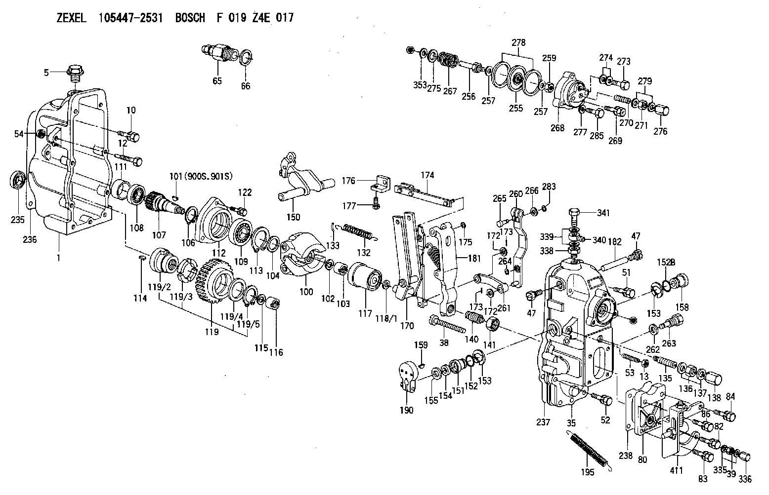
| 1. | [1] | 154002-4520 | GOVERNOR HOUSING |
| 5. | [1] | 154007-1600 | CAPSULE |
| 10. | [8] | 139006-4100 | BLEEDER SCREW |
| 12. | [1] | 154013-7200 | BLEEDER SCREW |
| 13. | [1] | 154011-5400 | UNION NUT |
| 35. | [1] | 154520-6920 | GOVERNOR COVER |
| 38. | [1] | 154031-3000 | FLAT-HEAD SCREW |
| 39. | [1] | 139206-0600 | UNION NUT |
| 47. | [2] | 154036-0300 | CAPSULE |
| 47. | [2] | 154036-0300 | CAPSULE |
| 51. | [4] | 020106-5040 | BLEEDER SCREW |
| 52. | [3] | 020106-2840 | BLEEDER SCREW |
| 53. | [1] | 154010-0300 | FLAT-HEAD SCREW |
| 54. | [1] | 154011-0100 | HEXAGON NUT |
| 65. | [1] | 153021-2220 | STOPPING DEVICE |
| 66. | [1] | 026524-3040 | GASKET |
| 80. | [1] | 154064-3500 | COVER |
| 82. | [1] | 029020-6260 | BLEEDER SCREW |
| 83. | [1] | 029020-6260 | BLEEDER SCREW |
| 84. | [1] | 029020-6260 | BLEEDER SCREW |
| 86. | [1] | 029020-6260 | BLEEDER SCREW |
| 100. | [1] | 154101-4620 | FLYWEIGHT ASSEMBLY |
| 101. | [1] | 025803-1610 | WOODRUFF KEY |
| 102. | [1] | 029321-2020 | LOCKING WASHER |
| 103. | [1] | 029231-2030 | UNION NUT |
| 104. | [1] | 154120-0100 | PLAIN WASHER |
| 106. | [1] | 029602-0020 | LOCKING WASHER |
| 107. | [1] | 154121-0500 | TOOTHED GEAR |
| 108. | [1] | 016610-2640 | BEARING PLATE |
| 109. | [1] | 028102-0010 | BEARING PLATE |
| 111. | [1] | 154134-0000 | SPACER BUSHING |
| 112. | [1] | 154122-0300 | COVER |
| 113. | [1] | 029614-7020 | LOCKING WASHER |
| 114. | [1] | 025803-1310 | WOODRUFF KEY |
| 115. | [1] | 029321-2020 | LOCKING WASHER |
| 116. | [1] | 029231-2030 | UNION NUT |
| 117. | [1] | 154123-1020 | SLIDING PIECE |
| 118/1. | [0] | 029311-0010 | SHIM D14&10.1T0.2 |
| 118/1. | [0] | 029311-0180 | SHIM D14&10.1T0.3 |
| 118/1. | [0] | 029311-0190 | SHIM D14&10.1T0.40 |
| 118/1. | [0] | 029311-0210 | SHIM D14&10.1T1 |
| 118/1. | [0] | 139410-0000 | SHIM D14.0&10.1T0.5 |
| 118/1. | [0] | 139410-0100 | SHIM D14.0&10.1T1.5 |
| 118/1. | [0] | 139410-3000 | SHIM D14&10.1T2.0 |
| 118/1. | [0] | 139410-3100 | SHIM D14&10.1T3.0 |
| 118/1. | [0] | 139410-3200 | SHIM D14&10.1T4.0 |
| 119. | [1] | 154130-1920 | TOOTHED GEAR |
| 119/2. | [1] | 154132-0320 | HOLDER |
| 119/3. | [4] | 153251-0600 | DAMPER |
| 119/4. | [1] | 139329-0000 | PLAIN WASHER |
| 119/5. | [1] | 016020-2810 | LOCKING WASHER |
| 122. | [3] | 020106-2840 | BLEEDER SCREW |
| 132. | [1] | 154154-3900 | COILED SPRING |
| 133. | [2] | 154156-0100 | TUBE |
| 135. | [1] | 154158-4720 | HEADLESS SCREW |
| 136. | [1] | 154371-3400 | UNION NUT |
| 137. | [2] | 026520-2440 | GASKET D23.9&20.2T1 |
| 138. | [1] | 154159-2000 | CAP NUT |
| 140. | [1] | 154176-4020 | HEADLESS SCREW |
| 141. | [1] | 029201-6010 | UNION NUT |
| 150. | [1] | 154200-6420 | SWIVELLING LEVER |
| 151. | [1] | 154204-4100 | BUSHING |
| 152. | [1] | 139718-0000 | O-RING |
| 152B. | [1] | 029631-6110 | O-RING |
| 153. | [2] | 016010-1640 | LOCKING WASHER |
| 153. | [2] | 016010-1640 | LOCKING WASHER |
| 154. | [1] | 029621-1070 | PACKING RING |
| 155. | [1] | 029311-1010 | SHIM |
| 158. | [1] | 154204-2200 | BUSHING |
| 159. | [1] | 025803-1310 | WOODRUFF KEY |
| 170. | [1] | 154217-2820 | FORK LEVER |
| 172. | [3] | 029310-5170 | SHIM D8&5.3T0.5 |
| 172. | [3] | 029310-5170 | SHIM D8&5.3T0.5 |
| 173. | [2] | 025520-1210 | SPLIT PIN |
| 173. | [2] | 025520-1210 | SPLIT PIN |
| 174. | [1] | 154230-0220 | STRAP |
| 175. | [1] | 016010-0540 | LOCKING WASHER |
| 176. | [1] | 154232-0400 | CONNECTOR |
| 177. | [2] | 029050-5040 | FLAT-HEAD SCREW M5P0.8L9 |
| 181. | [1] | 154239-2720 | TENSIONING LEVER |
| 182. | [1] | 154237-0200 | BEARING PIN |
| 190. | [1] | 154396-8220 | CONTROL LEVER |
| 195. | [1] | 154339-1100 | COILED SPRING |
| 235. | [1] | 029621-7010 | PACKING RING |
| 236. | [1] | 154371-5600 | GASKET |
| 237. | [1] | 154371-3500 | GASKET |
| 238. | [1] | 154371-3600 | GASKET |
| 255. | [1] | 154400-7820 | DIAPHRAGM |
| 256. | [1] | 154400-4800 | STOP PIN |
| 257. | [2] | 029330-8050 | GASKET |
| 257. | [2] | 029330-8050 | GASKET |
| 259. | [1] | 154372-7200 | HEXAGON NUT |
| 260. | [1] | 154401-4420 | CONTROL LEVER |
| 261. | [1] | 154401-1020 | STRAP |
| 262. | [1] | 026510-1440 | GASKET D13.9&10.2T1 |
| 263. | [1] | 154401-4500 | BLEEDER SCREW |
| 264. | [1] | 016010-0540 | LOCKING WASHER |
| 265. | [1] | 154222-6200 | BEARING PIN |
| 266. | [1] | 029300-4010 | PLAIN WASHER |
| 267. | [1] | 154416-0900 | COILED SPRING |
| 268. | [1] | 154404-5600 | COVER |
| 269. | [2] | 020106-2240 | BLEEDER SCREW |
| 270. | [1] | 154034-1900 | FLAT-HEAD SCREW |
| 271. | [1] | 013030-6040 | UNION NUT M6P1H3.6 |
| 273. | [1] | 029731-0120 | EYE BOLT |
| 274. | [2] | 029341-0110 | GASKET |
| 275. | [0] | 029312-0180 | SHIM D25.5&20T0.5 |
| 275B. | [0] | 029312-0210 | SHIM D25.5&20T0.2 |
| 276. | [1] | 154035-1600 | CAP NUT |
| 277. | [1] | 029320-6010 | LOCKING WASHER |
| 278. | [2] | 154413-2600 | GASKET |
| 279. | [2] | 026506-1040 | GASKET D9.9&6.2T1 |
| 283. | [1] | 016010-0440 | LOCKING WASHER |
| 285. | [1] | 029010-6310 | BLEEDER SCREW |
| 335. | [2] | 026506-1040 | GASKET D9.9&6.2T1 |
| 336. | [1] | 154035-1600 | CAP NUT |
| 338. | [1] | 131002-3800 | ADAPTOR |
| 339. | [2] | 029341-2140 | GASKET |
| 340. | [1] | 154373-1800 | INLET UNION |
| 341. | [1] | 154373-1700 | EYE BOLT |
| 353. | [3] | 029310-9080 | SHIM D16&9T1.7 |
| 411. | [1] | 154375-7720 | BRACKET |
| 900S. | [1] | 025803-1310 | WOODRUFF KEY |
| 901S. | [1] | 025803-1610 | WOODRUFF KEY |
Include in #1:
106685-4481
as GOVERNOR
Cross reference number
Zexel num
Bosch num
Firm num
Name
105447-2531
GOVERNOR
K 14JC MECHANICAL GOVERNOR GOV RSUV(D) GOV
K 14JC MECHANICAL GOVERNOR GOV RSUV(D) GOV
Information:
Disassembly
The following tools are needed: torque wrench, 16 millimeter socket or wrench, cotton swabs, rubbing alcohol, rubber gloves, small magnet, flashlight, plastic spray bottle and molykote or white lithium greaseThe following parts are supplied: two plugs for the outlet check valves, two outlet check valves, two springs and two ball studs
Ensure the proper cleanliness of hands and all parts before you begin the service procedure.
Check the engine serial number in order to ensure that the engine is correct for the service letter.
Steam clean the area that surrounds the plug for the outlet check valve or clean the area around the plug for the outlet check valve by flushing with rubbing alcohol.
The area must be cleaned with a towel that is soaked with alcohol in order to remove any other debris.
Inspect the area that is surrounding the plug for the outlet check valve in order to ensure that no debris is present.
Illustration 1 g01618509
Using a clean 16 millimeter socket or a wrench remove the plug for the outlet check valve.
Carefully remove the plug from the pump head. The spring is removed with the plug.
If the outlet check valve remains in the head, remove the check valve with the clean magnet.
Clean the threads and the area around the plug.Note: Soak the cotton swab with alcohol and insert the cotton swab into the threaded area. Use a counterclockwise rotation to clean the threaded area. Clean the spot face around the plug bore with a cotton swab that is soaked in alcohol. Clean the spot face around the plug bore in a counterclockwise rotation.
Illustration 2 g01626597
(1) Sealing surface of the pump bore
Look inside the pump bore in order to ensure that no debris that includes the debris from the cotton swab is on the sealing surface.
Repeat until the cotton swab is free of debris.
Illustration 3 g01618506
Assembly
Once parts have been removed, clean hands and put on clean rubber gloves.
When the parts are being installed in the pump, flush all the new parts with alcohol in order to ensure that no debris is on the parts.
Use a clean finger to apply clean molykote or white lithium grease to the surface that is being sealed and threads of plug.
Illustration 4 g01624087
Use clean molykote or white lithium grease in order to install the ball stud on the end of the spring. Press the ball stud and the spring together.
Illustration 5 g01624092
Insert the subassembly of the ball stud and the spring into the plug for the outlet check valve, with the end with the ball stud in the plug.Note: Be careful not to scratch the sealing surface of the plug for the outlet check valve.
Illustration 6 g01626602
(2) Sealing surface of the plug for the outlet check valve
Illustration 7 g01624154
(3) Gauge Pin
Illustration 8 g01624824
(4) Location of the ring groove on the gauge pin on a properly assembled ball stud and spring assembly
The distance between the end of the spring and the sealing surface of the plug for the outlet check valve should be checked with a gauge pin. The ring groove must be above the top