Information governor
BOSCH
F 019 Z2E 960
f019z2e960
ZEXEL
105447-2441
1054472441
Rating:
Scheme ###:
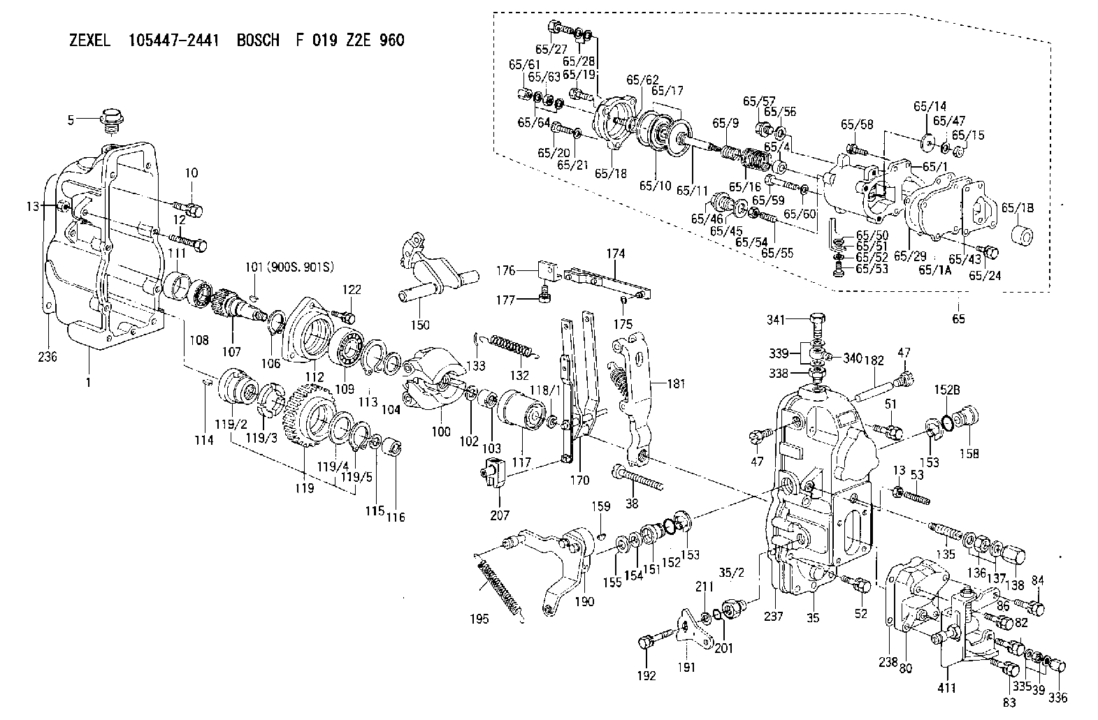
| 1. | [1] | 154002-4420 | GOVERNOR HOUSING |
| 5. | [1] | 154007-1600 | CAPSULE |
| 10. | [8] | 139006-4100 | BLEEDER SCREW |
| 12. | [1] | 154010-3900 | BLEEDER SCREW |
| 13. | [2] | 154011-0100 | HEXAGON NUT |
| 13. | [2] | 154011-0100 | HEXAGON NUT |
| 35. | [1] | 154023-4520 | GOVERNOR COVER |
| 35/2. | [1] | 154321-0200 | BUSHING |
| 38. | [1] | 154031-4400 | FLAT-HEAD SCREW |
| 39. | [1] | 139206-0600 | UNION NUT |
| 47. | [2] | 154036-0300 | CAPSULE |
| 47. | [2] | 154036-0300 | CAPSULE |
| 51. | [4] | 020106-5040 | BLEEDER SCREW |
| 52. | [3] | 020106-2840 | BLEEDER SCREW |
| 53. | [1] | 154010-0300 | FLAT-HEAD SCREW |
| 65. | [1] | 154422-7220 | MANIFOLD-PRESSURE COMP. |
| 65/1. | [1] | 154412-0020 | GOVERNOR HOUSING |
| 65/1A. | [1] | 154408-2901 | SPACER BUSHING |
| 65/1B. | [1] | 134009-0000 | SPACER BUSHING |
| 65/4. | [1] | 154413-1400 | BUSHING |
| 65/9. | [1] | 154412-4300 | COILED SPRING |
| 65/10. | [1] | 154400-8220 | DIAPHRAGM |
| 65/11. | [1] | 154400-6101 | STOP PIN |
| 65/14. | [1] | 154406-5500 | SLOTTED WASHER |
| 65/15. | [1] | 013020-6040 | UNION NUT M6P1H5 |
| 65/16. | [1] | 154402-0200 | COILED SPRING |
| 65/17. | [2] | 154413-2600 | GASKET |
| 65/18. | [1] | 154404-5000 | COVER |
| 65/19. | [1] | 020106-2040 | BLEEDER SCREW M6P1L20 |
| 65/20. | [2] | 029010-6310 | BLEEDER SCREW |
| 65/21. | [2] | 014110-6440 | LOCKING WASHER |
| 65/24. | [2] | 020106-2040 | BLEEDER SCREW M6P1L20 |
| 65/27. | [1] | 029731-0180 | EYE BOLT |
| 65/28. | [2] | 029341-0110 | GASKET |
| 65/29. | [1] | 154390-1700 | GASKET |
| 65/43. | [1] | 154390-1800 | GASKET |
| 65/45. | [1] | 029331-8040 | GASKET |
| 65/46. | [1] | 154406-5800 | FLAT-HEAD SCREW |
| 65/47. | [1] | 014110-6440 | LOCKING WASHER |
| 65/50. | [1] | 154406-6800 | PLAIN WASHER |
| 65/51. | [1] | 154406-6901 | CONTROL LEVER |
| 65/52. | [1] | 014110-4440 | LOCKING WASHER |
| 65/53. | [1] | 010234-0820 | HEX-SOCKET-HEAD CAP SCREW |
| 65/54. | [1] | 013030-6040 | UNION NUT M6P1H3.6 |
| 65/55. | [1] | 154404-1600 | FLAT-HEAD SCREW L26.00 |
| 65/56. | [1] | 029331-2130 | GASKET |
| 65/57. | [1] | 154406-6500 | FLAT-HEAD SCREW |
| 65/58. | [2] | 020106-2540 | BLEEDER SCREW M6P1L25 |
| 65/59. | [2] | 010006-7040 | BLEEDER SCREW M6P1L70 |
| 65/60. | [2] | 014110-6440 | LOCKING WASHER |
| 65/61. | [1] | 154035-1600 | CAP NUT |
| 65/62. | [1] | 154404-4400 | FLAT-HEAD SCREW |
| 65/63. | [1] | 013030-6040 | UNION NUT M6P1H3.6 |
| 65/64. | [2] | 026506-1040 | GASKET D9.9&6.2T1 |
| 80. | [1] | 154064-3800 | COVER |
| 82. | [1] | 139006-2500 | BLEEDER SCREW M6P1.0L23 |
| 83. | [1] | 139006-2500 | BLEEDER SCREW M6P1.0L23 |
| 84. | [1] | 029020-6290 | BLEEDER SCREW |
| 86. | [1] | 029020-6290 | BLEEDER SCREW |
| 100. | [1] | 154100-9920 | FLYWEIGHT ASSEMBLY |
| 101. | [1] | 025803-1610 | WOODRUFF KEY |
| 102. | [1] | 029321-2020 | LOCKING WASHER |
| 103. | [1] | 029231-2030 | UNION NUT |
| 104. | [1] | 154120-0100 | PLAIN WASHER |
| 106. | [1] | 029602-0020 | LOCKING WASHER |
| 107. | [1] | 154121-0500 | TOOTHED GEAR |
| 108. | [1] | 016610-2640 | BEARING PLATE |
| 109. | [1] | 028102-0010 | BEARING PLATE |
| 111. | [1] | 154134-0000 | SPACER BUSHING |
| 112. | [1] | 154122-0300 | COVER |
| 113. | [1] | 029614-7020 | LOCKING WASHER |
| 114. | [1] | 025803-1310 | WOODRUFF KEY |
| 115. | [1] | 029321-2020 | LOCKING WASHER |
| 116. | [1] | 029231-2030 | UNION NUT |
| 117. | [1] | 154123-1020 | SLIDING PIECE |
| 118/1. | [0] | 029311-0010 | SHIM D14&10.1T0.2 |
| 118/1. | [0] | 029311-0180 | SHIM D14&10.1T0.3 |
| 118/1. | [0] | 029311-0190 | SHIM D14&10.1T0.40 |
| 118/1. | [0] | 029311-0210 | SHIM D14&10.1T1 |
| 118/1. | [0] | 139410-0000 | SHIM D14.0&10.1T0.5 |
| 118/1. | [0] | 139410-0100 | SHIM D14.0&10.1T1.5 |
| 118/1. | [0] | 139410-3000 | SHIM D14&10.1T2.0 |
| 118/1. | [0] | 139410-3100 | SHIM D14&10.1T3.0 |
| 118/1. | [0] | 139410-3200 | SHIM D14&10.1T4.0 |
| 119. | [1] | 154130-1820 | TOOTHED GEAR |
| 119/2. | [1] | 154132-0320 | HOLDER |
| 119/3. | [4] | 153251-0100 | DAMPER |
| 119/4. | [1] | 139329-0000 | PLAIN WASHER |
| 119/5. | [1] | 016020-2810 | LOCKING WASHER |
| 122. | [3] | 020106-2840 | BLEEDER SCREW |
| 132. | [1] | 154154-4200 | COILED SPRING |
| 133. | [2] | 154156-0100 | TUBE |
| 135. | [1] | 154158-0620 | HEADLESS SCREW |
| 136. | [1] | 029201-2290 | UNION NUT |
| 137. | [2] | 026512-1540 | GASKET D15.4&12.2T1.50 |
| 138. | [1] | 154159-1200 | CAP NUT |
| 150. | [1] | 154200-4520 | SWIVELLING LEVER |
| 151. | [1] | 154204-4100 | BUSHING |
| 152. | [1] | 139718-0200 | O-RING |
| 152B. | [1] | 139716-0100 | O-RING |
| 153. | [2] | 016010-1640 | LOCKING WASHER |
| 153. | [2] | 016010-1640 | LOCKING WASHER |
| 154. | [1] | 139611-0200 | PACKING RING |
| 155. | [1] | 029311-1010 | SHIM |
| 158. | [1] | 154204-2200 | BUSHING |
| 159. | [1] | 025803-1310 | WOODRUFF KEY |
| 170. | [1] | 154211-7620 | FORK LEVER |
| 174. | [1] | 154235-2720 | STRAP |
| 175. | [1] | 016010-0540 | LOCKING WASHER |
| 176. | [1] | 154232-0400 | CONNECTOR |
| 177. | [2] | 029050-5040 | FLAT-HEAD SCREW M5P0.8L9 |
| 181. | [1] | 154236-5721 | TENSIONING LEVER |
| 182. | [1] | 154237-0200 | BEARING PIN |
| 190. | [1] | 154395-5420 | CONTROL LEVER |
| 191. | [1] | 154383-0300 | CONTROL LEVER |
| 192. | [1] | 020006-1670 | BLEEDER SCREW M6P1L16 7T |
| 195. | [1] | 154332-3200 | COILED SPRING |
| 201. | [1] | 139710-0400 | O-RING |
| 207. | [1] | 154326-8320 | LEVER GROUP |
| 211. | [0] | 029311-0220 | SHIM D18&10.3T0.2 |
| 211B. | [0] | 029311-0230 | SHIM D18&10.3T0.5 |
| 236. | [1] | 154371-5600 | GASKET |
| 237. | [1] | 154371-3500 | GASKET |
| 238. | [1] | 154390-3500 | GASKET |
| 335. | [2] | 026506-1040 | GASKET D9.9&6.2T1 |
| 336. | [1] | 154035-1600 | CAP NUT |
| 338. | [1] | 131002-3800 | ADAPTOR |
| 339. | [2] | 029341-2140 | GASKET |
| 340. | [1] | 154373-1800 | INLET UNION |
| 341. | [1] | 154373-1700 | EYE BOLT |
| 411. | [1] | 154375-9320 | BRACKET |
| 900S. | [1] | 025803-1310 | WOODRUFF KEY |
| 901S. | [1] | 025803-1610 | WOODRUFF KEY |
Cross reference number
Zexel num
Bosch num
Firm num
Name
Information:
Illustration 13 g02915447
Plugged DOC
The DOC utilizes a “pass-through” technology, which is different from the “wall flow” design of a DPF. When a light is shined through the DOC, a visible light should be able to pass through. Utilize a flashlight to check for a plugged DOC face. Aim the flashlight into the DOC inlet, visible light should be seen through the DOC. A plugged DOC can be caused by high oil consumption, not recommended fuel additives, or wrong engine oil types. Refer to the Operation and Maintenance Manual for recommended fluids to use. If light cannot be seen on the outlet of the DOC, then replace the DOC.CRS Bodies
Illustration 14 g06342815
Combustion Group
(1) Head Group - Combustion
(2) Gasket
(3) Tube
(4) Body Assembly - Exhaust CombustionCRS Combustion Body (4) contains the flame necessary for CRS Regeneration. There are two combustion stages that occur within the CRS Body: the primary and secondary combustion. The primary combustion of air and fuel occur within Tube (3) to create the CRS flame immediately following Head Group (1). The secondary combustion of the CRS flame and exhaust gas from the turbocharger occur within Body Assembly (4).The body assembly is the only salvageable part of the combustion group. The body assembly must be cleaned, inspected, and pressure tested prior to reuse.Cleaning
Start by isolating the CRS body from all other CRS exhaust components. Remove the head group, the mounting studs, the tube, and the two gaskets.The gasket area and the bellows joints are the two areas of the CRS body that must be cleaned thoroughly to make a proper seal.Cleaning the remainder of the CRS body is not required. If cleaning the CRS body is desired, then first perform the visual inspection, vacuum inspection, and welding procedures prior to washing the CRS body. This step is to ensure that the CRS body is salvageable, not cracked, and to keep water from getting trapped behind the heat shield.If washing is preferred, then use soap and water as a cleaning solution. Do not submerge the CRS body to prevent water from becoming trapped between the heat shield and the CRS body. A cylinder washing brush, a wire brush with handle, and a greenScotch Brite pads are all acceptable cleaning equipment. Removal of all diesel particulates is not required for inspection.
Do not use any combustible solvents to clean the CRS body.
Visual Inspection
A visual inspection of the CRS body must be completed, special equipment or crack detecting solution is not required. Visually inspect the exterior of the CRS body. Small cracks and/or punctures found on the stainless steel heat shield is normal and should be expected. Inspect the bellows sealing joints and the CRS head mating surface for visual damage.Light surface rust is typically not a problem unless rust is found on a bellows joint or the CRS gasket mating surface. Light rust in these two areas must be removed using a Scotch Brite pad.Serviceability
All bolts, studs, and clamps are not reusable and must be replaced with new components.Any thread damage in the mounting