Information governor
BOSCH
F 019 Z2F 171
f019z2f171
ZEXEL
105447-1982
1054471982
Rating:
Scheme ###:
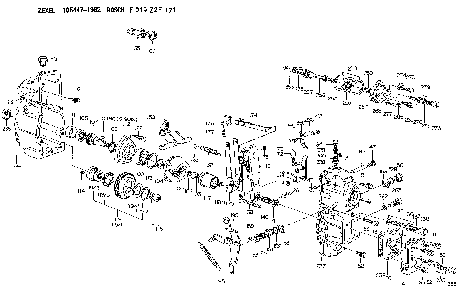
| 1. | [1] | 154002-4520 | GOVERNOR HOUSING |
| 5. | [1] | 154007-1600 | CAPSULE |
| 10. | [8] | 139006-4100 | BLEEDER SCREW |
| 12. | [1] | 154010-3900 | BLEEDER SCREW |
| 13. | [2] | 154011-0100 | HEXAGON NUT |
| 13. | [2] | 154011-0100 | HEXAGON NUT |
| 35. | [1] | 154520-6920 | GOVERNOR COVER |
| 38. | [1] | 154031-3000 | FLAT-HEAD SCREW |
| 39. | [1] | 139206-0600 | UNION NUT |
| 47. | [2] | 154036-0300 | CAPSULE |
| 47. | [2] | 154036-0300 | CAPSULE |
| 51. | [4] | 020106-5040 | BLEEDER SCREW |
| 52. | [3] | 020106-2840 | BLEEDER SCREW |
| 53. | [1] | 154010-0300 | FLAT-HEAD SCREW M8.P1.25.L40 |
| 65. | [1] | 153021-3120 | STOPPING DEVICE |
| 66. | [1] | 026524-3040 | GASKET |
| 80. | [1] | 154064-3500 | COVER |
| 82. | [1] | 029020-6260 | BLEEDER SCREW |
| 83. | [1] | 029020-6260 | BLEEDER SCREW |
| 84. | [1] | 029020-6260 | BLEEDER SCREW |
| 86. | [1] | 029020-6260 | BLEEDER SCREW |
| 100. | [1] | 154101-4620 | FLYWEIGHT ASSEMBLY |
| 101. | [1] | 025803-1610 | WOODRUFF KEY 16 MM |
| 102. | [1] | 029321-2020 | LOCKING WASHER |
| 103. | [1] | 029231-2030 | UNION NUT |
| 104. | [1] | 154120-0100 | PLAIN WASHER |
| 106. | [1] | 029602-0020 | LOCKING WASHER |
| 107. | [1] | 154121-0500 | TOOTHED GEAR |
| 108. | [1] | 016610-2640 | BEARING PLATE |
| 109. | [1] | 028102-0010 | BEARING PLATE |
| 111. | [1] | 154134-0000 | SPACER BUSHING |
| 112. | [1] | 154122-0300 | COVER |
| 113. | [1] | 029614-7020 | LOCKING WASHER |
| 114. | [1] | 025803-1310 | WOODRUFF KEY 13 MM |
| 115. | [1] | 029321-2020 | LOCKING WASHER |
| 116. | [1] | 029231-2030 | UNION NUT |
| 117. | [1] | 154123-1020 | SLIDING PIECE |
| 118/1. | [0] | 029311-0010 | SHIM D14&10.1T0.2 |
| 118/1. | [0] | 029311-0180 | SHIM D14&10.1T0.3 |
| 118/1. | [0] | 029311-0190 | SHIM D14&10.1T0.40 |
| 118/1. | [0] | 029311-0210 | SHIM D14&10.1T1 |
| 118/1. | [0] | 139410-0000 | SHIM D14&10.1T0.5 |
| 118/1. | [0] | 139410-0100 | SHIM D14&10.1T1.5 |
| 118/1. | [0] | 139410-3000 | SHIM D14&10.1T2.0 |
| 118/1. | [0] | 139410-3100 | SHIM D14&10.1T3.0 |
| 118/1. | [0] | 139410-3200 | SHIM D14&10.1T4.0 |
| 119. | [1] | 154130-1820 | TOOTHED GEAR |
| 119/1. | [1] | 154130-0510 | TOOTHED GEAR |
| 119/2. | [1] | 154132-0320 | HOLDER |
| 119/3. | [4] | 153251-0100 | DAMPER |
| 119/4. | [1] | 139329-0000 | PLAIN WASHER |
| 119/5. | [1] | 016020-2810 | LOCKING WASHER |
| 122. | [3] | 020106-2840 | BLEEDER SCREW |
| 132. | [1] | 154154-3900 | COILED SPRING |
| 133. | [2] | 154156-0100 | TUBE |
| 135. | [1] | 154158-4720 | HEADLESS SCREW |
| 136. | [1] | 154371-3400 | UNION NUT |
| 137. | [2] | 026520-2440 | GASKET |
| 138. | [1] | 154159-2000 | CAP NUT |
| 140. | [1] | 154185-3120 | HEADLESS SCREW |
| 141. | [1] | 029201-6010 | UNION NUT |
| 150. | [1] | 154200-6420 | SWIVELLING LEVER |
| 151. | [1] | 154204-4100 | BUSHING |
| 152. | [1] | 139718-0200 | O-RING |
| 152B. | [1] | 139716-0100 | O-RING |
| 153. | [2] | 016010-1640 | LOCKING WASHER |
| 153. | [2] | 016010-1640 | LOCKING WASHER |
| 154. | [1] | 139611-0200 | PACKING RING |
| 155. | [1] | 029311-1010 | SHIM |
| 158. | [1] | 154204-2200 | BUSHING |
| 159. | [1] | 025803-1310 | WOODRUFF KEY 13 MM |
| 170. | [1] | 154217-2820 | FORK LEVER |
| 172. | [3] | 029310-5170 | SHIM |
| 172. | [3] | 029310-5170 | SHIM |
| 173. | [2] | 025520-1210 | SPLIT PIN |
| 173. | [2] | 025520-1210 | SPLIT PIN |
| 174. | [1] | 154230-0220 | STRAP |
| 175. | [1] | 016010-0540 | LOCKING WASHER |
| 176. | [1] | 154232-0400 | CONNECTOR |
| 177. | [2] | 029050-5040 | FLAT-HEAD SCREW |
| 181. | [1] | 154239-2720 | TENSIONING LEVER |
| 182. | [1] | 154237-0200 | BEARING PIN |
| 190. | [1] | 154396-1020 | CONTROL LEVER |
| 195. | [1] | 154332-3200 | COILED SPRING |
| 235. | [1] | 029621-7010 | PACKING RING |
| 236. | [1] | 154371-5600 | GASKET |
| 237. | [1] | 154371-3500 | GASKET |
| 238. | [1] | 154371-3600 | GASKET |
| 255. | [1] | 154400-7420 | DIAPHRAGM |
| 256. | [1] | 154400-4800 | STOP PIN |
| 257. | [2] | 029330-8050 | GASKET |
| 257. | [2] | 029330-8050 | GASKET |
| 259. | [1] | 154372-7200 | HEXAGON NUT |
| 260. | [1] | 154401-4420 | CONTROL LEVER |
| 261. | [1] | 154401-1020 | STRAP |
| 262. | [1] | 026510-1440 | GASKET |
| 263. | [1] | 154401-4500 | BLEEDER SCREW |
| 264. | [1] | 016010-0540 | LOCKING WASHER |
| 265. | [1] | 154222-6200 | BEARING PIN |
| 266. | [1] | 029300-4010 | PLAIN WASHER |
| 267. | [1] | 154411-2100 | COILED SPRING |
| 268. | [1] | 154404-5600 | COVER |
| 269. | [2] | 020106-2240 | BLEEDER SCREW |
| 270. | [1] | 154034-1900 | FLAT-HEAD SCREW |
| 271. | [1] | 013030-6040 | UNION NUT |
| 273. | [1] | 029731-0120 | EYE BOLT |
| 274. | [2] | 029341-0110 | GASKET |
| 275. | [0] | 029312-0180 | SHIM D25.5&20T0.5 |
| 275B. | [0] | 029312-0210 | SHIM D25.5&20T0.2 |
| 276. | [1] | 154035-1600 | CAP NUT |
| 277. | [1] | 029320-6010 | LOCKING WASHER |
| 278. | [2] | 154413-2600 | GASKET |
| 279. | [2] | 026506-1040 | GASKET |
| 283. | [1] | 016010-0440 | LOCKING WASHER |
| 285. | [1] | 029010-6310 | BLEEDER SCREW |
| 335. | [2] | 026506-1040 | GASKET |
| 336. | [1] | 154035-1600 | CAP NUT |
| 338. | [1] | 131002-3800 | ADAPTOR |
| 339. | [2] | 029341-2140 | GASKET |
| 340. | [1] | 154373-1800 | INLET UNION |
| 341. | [1] | 154373-1700 | EYE BOLT |
| 353. | [1] | 029310-9080 | SHIM |
| 411. | [1] | 154375-7120 | BRACKET |
| 900S. | [1] | 025803-1310 | WOODRUFF KEY 13 MM |
| 901S. | [1] | 025803-1610 | WOODRUFF KEY 16 MM |
Include in #1:
106682-9572
as GOVERNOR
Cross reference number
Zexel num
Bosch num
Firm num
Name
Information:
Introduction
This Special Instruction covers the removal procedure for DEF connectors on the models and applications listed above.Safety Section
Care must be taken to ensure that fluids are contained during performance of inspection, maintenance, testing, adjusting, and repair of the product. Be prepared to collect the fluid with suitable containers before opening any compartment or disassembling any component containing fluids.Refer to Special Publication, PERJ1017, "Dealer Service Tool Catalog" for tools and supplies suitable to collect and contain fluids on Cat® products.Dispose of all fluids according to local regulations and mandates.
Personal injury or death can result from improperly checking for a leak.Always use a board or cardboard when checking for a leak. Escaping air or fluid under pressure, even a pin-hole size leak, can penetrate body tissue causing serious injury, and possible death.If fluid is injected into your skin, it must be treated immediately by a doctor familiar with this type of injury.
Illustration 1 g00104545Prevent the machine from movement. Park the machine on a level surface.Attach a "Do Not Operate" warning tag or a similar warning tag to the start switch or to the controls before you service the equipment. These warning tags (Special Instruction, SEHS7332) are available from your Caterpillar dealer.Removal Procedure for Single Clip Connectors
Illustration 2 g03468077
(1) Line
(2) Retaining Clip
Clean the area around the connector with compressed air. Be sure to remove any dirt or debris before continuing with this procedure.
Press down on the line (1).
Press IN on the retaining clip (2).
Gently pull straight up on the line.Note: Do not pull out the clip, damage will occur to the retaining clip.Note: Do not pull off the line without the clip being fully depressed, damage will occur to the retaining clip.Removal Procedure for Dual Clip Connectors
Illustration 3 g03468506
(1) Line
(2) Retaining Clips
Clean the area around the connector with compressed air. Be sure to remove any dirt or debris before continuing with this procedure.
Press down on the line (1).
Press IN on the retaining clips (2).
Gently pull straight up on the line.Note: Do not pull out the clip, damage will occur to the retaining clip.Note: Do not pull off the line without the clip being fully depressed, damage will occur to the retaining clip.