Information governor
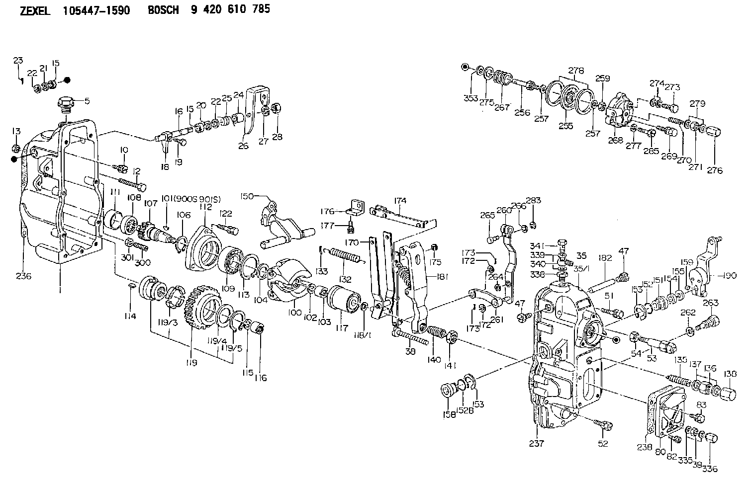
BOSCH
9 420 610 785
9420610785
ZEXEL
105447-1590
1054471590
Rating:
Scheme ###:
| 1. | [1] | 154002-3520 | GOVERNOR HOUSING |
| 5. | [1] | 154007-1600 | CAPSULE |
| 10. | [8] | 139006-4100 | BLEEDER SCREW |
| 12. | [1] | 154010-3900 | BLEEDER SCREW |
| 13. | [2] | 154011-0100 | HEXAGON NUT |
| 15. | [2] | 139608-0200 | PACKING RING |
| 15. | [2] | 139608-0200 | PACKING RING |
| 16. | [1] | 155004-4900 | LEVER SHAFT |
| 18. | [1] | 155003-3100 | CONTROL LEVER |
| 19. | [1] | 155006-0700 | BLEEDER SCREW |
| 20. | [1] | 139308-1100 | PLAIN WASHER |
| 21. | [0] | 029310-8050 | SHIM D13.5&8T0.5 |
| 22. | [0] | 029310-8050 | SHIM D13.5&8T0.5 |
| 22. | [0] | 029310-8050 | SHIM D13.5&8T0.5 |
| 23. | [1] | 155402-3800 | SAFETY PIN |
| 24. | [1] | 154206-2000 | BUSHING |
| 25. | [1] | 154327-4200 | COILED SPRING |
| 26. | [1] | 154382-2000 | CONTROL LEVER |
| 27. | [1] | 014110-8440 | LOCKING WASHER |
| 28. | [1] | 013020-8040 | UNION NUT M8P1.25H7 |
| 35. | [1] | 154520-8020 | GOVERNOR COVER |
| 35/1. | [1] | 154520-8000 | GOVERNOR COVER |
| 38. | [1] | 154031-3000 | FLAT-HEAD SCREW |
| 39. | [1] | 139206-0600 | UNION NUT |
| 47. | [2] | 154036-0300 | CAPSULE |
| 47. | [2] | 154036-0300 | CAPSULE |
| 51. | [4] | 020106-5040 | BLEEDER SCREW |
| 52. | [3] | 020106-2840 | BLEEDER SCREW |
| 53. | [1] | 154013-0720 | HEADLESS SCREW |
| 54. | [1] | 154011-1900 | UNION NUT |
| 80. | [1] | 154063-0900 | COVER |
| 82. | [2] | 029020-6210 | BLEEDER SCREW |
| 83. | [2] | 020006-1640 | BLEEDER SCREW M6P1L16 4T |
| 100. | [1] | 154100-9720 | FLYWEIGHT ASSEMBLY |
| 101. | [1] | 025803-1310 | WOODRUFF KEY |
| 102. | [1] | 029321-2020 | LOCKING WASHER |
| 103. | [1] | 029231-2030 | UNION NUT |
| 104. | [1] | 154120-0100 | PLAIN WASHER |
| 106. | [1] | 029602-0020 | LOCKING WASHER |
| 107. | [1] | 154121-0500 | TOOTHED GEAR |
| 108. | [1] | 016610-2640 | BEARING PLATE |
| 109. | [1] | 028102-0010 | BEARING PLATE |
| 111. | [1] | 154134-0000 | SPACER BUSHING |
| 112. | [1] | 154122-0300 | COVER |
| 113. | [1] | 029614-7020 | LOCKING WASHER |
| 114. | [1] | 025803-1610 | WOODRUFF KEY |
| 115. | [1] | 029321-2020 | LOCKING WASHER |
| 116. | [1] | 029231-2030 | UNION NUT |
| 117. | [1] | 154123-1020 | SLIDING PIECE |
| 118/1. | [0] | 029311-0010 | SHIM D14&10.1T0.2 |
| 118/1. | [0] | 029311-0180 | SHIM D14&10.1T0.3 |
| 118/1. | [0] | 029311-0190 | SHIM D14&10.1T0.40 |
| 118/1. | [0] | 029311-0210 | SHIM D14&10.1T1 |
| 118/1. | [0] | 139410-0000 | SHIM D14.0&10.1T0.5 |
| 118/1. | [0] | 139410-0100 | SHIM D14.0&10.1T1.5 |
| 118/1. | [0] | 139410-3000 | SHIM D14&10.1T2.0 |
| 118/1. | [0] | 139410-3100 | SHIM D14&10.1T3.0 |
| 118/1. | [0] | 139410-3200 | SHIM D14&10.1T4.0 |
| 119. | [1] | 154130-1820 | TOOTHED GEAR |
| 119/3. | [4] | 153251-0100 | DAMPER |
| 119/4. | [1] | 139329-0000 | PLAIN WASHER |
| 119/5. | [1] | 016020-2810 | LOCKING WASHER |
| 122. | [3] | 020106-2840 | BLEEDER SCREW |
| 132. | [1] | 154154-2900 | COILED SPRING |
| 133. | [2] | 154156-0100 | TUBE |
| 135. | [1] | 154158-0620 | HEADLESS SCREW |
| 136. | [1] | 029201-2290 | UNION NUT |
| 137. | [2] | 026512-1540 | GASKET D15.4&12.2T1.50 |
| 138. | [1] | 154159-1200 | CAP NUT |
| 140. | [1] | 154186-1320 | HEADLESS SCREW |
| 141. | [1] | 029201-6010 | UNION NUT |
| 150. | [1] | 154200-7520 | SWIVELLING LEVER |
| 151. | [1] | 154204-4100 | BUSHING |
| 152. | [1] | 139718-0200 | O-RING |
| 152B. | [1] | 139716-0100 | O-RING |
| 153. | [2] | 016010-1640 | LOCKING WASHER |
| 153. | [2] | 016010-1640 | LOCKING WASHER |
| 154. | [1] | 139611-0200 | PACKING RING |
| 155. | [1] | 029311-1010 | SHIM |
| 158. | [1] | 154204-2200 | BUSHING |
| 159. | [1] | 025803-1310 | WOODRUFF KEY |
| 170. | [1] | 154217-2820 | FORK LEVER |
| 172. | [3] | 029310-5170 | SHIM D8&5.3T0.5 |
| 172. | [3] | 029310-5170 | SHIM D8&5.3T0.5 |
| 173. | [2] | 025520-1210 | SPLIT PIN |
| 173. | [2] | 025520-1210 | SPLIT PIN |
| 174. | [1] | 154234-9220 | STRAP |
| 175. | [1] | 016010-0540 | LOCKING WASHER |
| 176. | [1] | 154232-2700 | CONNECTOR |
| 177. | [2] | 029050-5040 | FLAT-HEAD SCREW M5P0.8L9 |
| 181. | [1] | 154239-2720 | TENSIONING LEVER |
| 182. | [1] | 154237-0200 | BEARING PIN |
| 190. | [1] | 154395-4820 | CONTROL LEVER |
| 236. | [1] | 154371-5600 | GASKET |
| 237. | [1] | 154371-3500 | GASKET |
| 238. | [1] | 154390-3500 | GASKET |
| 255. | [1] | 154400-7420 | DIAPHRAGM |
| 256. | [1] | 154400-4800 | STOP PIN |
| 257. | [2] | 029330-8050 | GASKET |
| 257. | [2] | 029330-8050 | GASKET |
| 259. | [1] | 154372-7200 | HEXAGON NUT |
| 260. | [1] | 154401-4420 | CONTROL LEVER |
| 261. | [1] | 154401-1020 | STRAP |
| 262. | [1] | 026510-1440 | GASKET D13.9&10.2T1 |
| 263. | [1] | 154401-4500 | BLEEDER SCREW |
| 264. | [1] | 016010-0540 | LOCKING WASHER |
| 265. | [1] | 154222-6200 | BEARING PIN |
| 266. | [1] | 029300-4010 | PLAIN WASHER |
| 267. | [1] | 154403-7200 | COILED SPRING |
| 268. | [1] | 154404-5000 | COVER |
| 269. | [2] | 020106-2240 | BLEEDER SCREW |
| 270. | [1] | 154034-1900 | FLAT-HEAD SCREW |
| 271. | [1] | 013030-6040 | UNION NUT M6P1H3.6 |
| 273. | [1] | 029731-0120 | EYE BOLT |
| 274. | [2] | 029341-0110 | GASKET |
| 275. | [0] | 029312-0180 | SHIM D25.5&20T0.5 |
| 275B. | [0] | 029312-0210 | SHIM D25.5&20T0.2 |
| 276. | [1] | 154035-1600 | CAP NUT |
| 277. | [1] | 029320-6010 | LOCKING WASHER |
| 278. | [2] | 154413-2600 | GASKET |
| 279. | [2] | 026506-1040 | GASKET D9.9&6.2T1 |
| 283. | [1] | 016010-0440 | LOCKING WASHER |
| 285. | [1] | 029010-6310 | BLEEDER SCREW |
| 300. | [1] | 154010-0300 | FLAT-HEAD SCREW |
| 301. | [1] | 154011-0100 | HEXAGON NUT |
| 335. | [2] | 026506-1040 | GASKET D9.9&6.2T1 |
| 336. | [1] | 154035-1600 | CAP NUT |
| 338. | [1] | 131002-3800 | ADAPTOR |
| 339. | [2] | 029341-2140 | GASKET |
| 340. | [1] | 154373-1800 | INLET UNION |
| 341. | [1] | 154373-1700 | EYE BOLT |
| 353. | [2] | 029310-9080 | SHIM D16&9T1.7 |
| 900S. | [1] | 025803-1310 | WOODRUFF KEY |
| 901S. | [1] | 025803-1610 | WOODRUFF KEY |
Include in #1:
106682-9151
as GOVERNOR
Cross reference number
Zexel num
Bosch num
Firm num
Name
105447-1590
GOVERNOR
K 14JC MECHANICAL GOVERNOR GOV RSUV(D) GOV
K 14JC MECHANICAL GOVERNOR GOV RSUV(D) GOV
Information:
Illustration 1 g00858201
(1) PCI Slot (2) Shared PCI/ISA Slot (3) DIMM Memory (4) Slot Cover (5) I/O Card Slot (6) CPU Slot (7) ScrewIn order to install the CPU board, perform the following procedure:
Remove the board from the anti-static packaging. Place the board on a ground, static free surface.
Illustration 2 g00858199
(8) Jumper JP2
The instructions for the board explain the locations of any jumpers or switches that need to be placed.Note: If you are replacing the CPU board, make a careful note of the cables that are attached to the existing CPU board. This will help you reconnect the cables to the new board.Note: The CPU board contains a video jumper setting that is specific to each version of the monitor. If jumper JP2 (8) is set incorrectly, the monitor video circuitry may be damaged.
Hold the board by the edges. Press the board firmly into the connector on the processor board.Note: Do not disturb the air flow director. The air flow director is required in order to keep the CPU cool. The air flow director should be routed behind the two add-in card slots. The air flow director should extend alongside the CPU heatsink.
Illustration 3 g00860148
(9) Board Retainer (10) Screw
Align the notch in the board retainer with the threaded hole. Install the screw. Hold the notch tightly against the screw before you tighten the screw.Note: Install the retainer tightly against the screw. If the retainer is not correctly installed, problems may occur when you insert an adjacent board.