Information governor
BOSCH
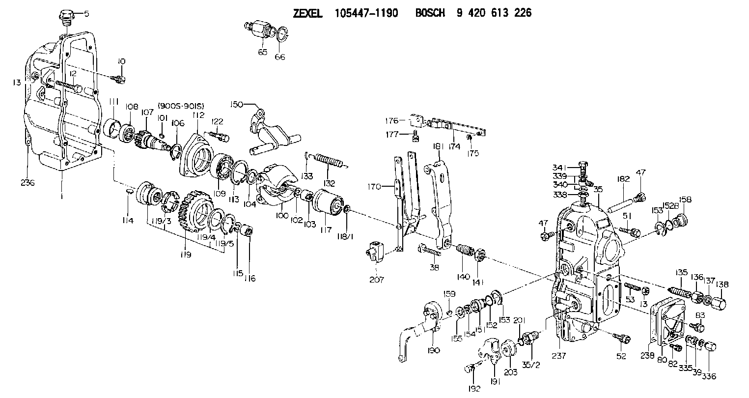
9 420 613 226
9420613226
ZEXEL
105447-1190
1054471190
Rating:
Scheme ###:
| 1. | [1] | 154002-3320 | GOVERNOR HOUSING |
| 5. | [1] | 154007-1600 | CAPSULE |
| 10. | [8] | 139006-4100 | BLEEDER SCREW |
| 12. | [1] | 154010-3900 | BLEEDER SCREW |
| 13. | [2] | 154011-0100 | HEXAGON NUT |
| 13. | [2] | 154011-0100 | HEXAGON NUT |
| 35. | [1] | 154520-7120 | GOVERNOR COVER |
| 35/2. | [1] | 154321-0200 | BUSHING |
| 38. | [1] | 154031-3800 | FLAT-HEAD SCREW |
| 39. | [1] | 139206-0600 | UNION NUT |
| 47. | [2] | 154036-0300 | CAPSULE |
| 47. | [2] | 154036-0300 | CAPSULE |
| 51. | [4] | 020106-5040 | BLEEDER SCREW |
| 52. | [3] | 020106-2840 | BLEEDER SCREW |
| 53. | [1] | 154010-0100 | FLAT-HEAD SCREW |
| 65. | [1] | 153021-3120 | STOPPING DEVICE |
| 66. | [1] | 026524-3040 | GASKET |
| 80. | [1] | 154063-0900 | COVER |
| 82. | [2] | 029020-6210 | BLEEDER SCREW |
| 83. | [2] | 020006-1640 | BLEEDER SCREW M6P1L16 4T |
| 100. | [1] | 154100-9720 | FLYWEIGHT ASSEMBLY |
| 101. | [1] | 025803-1310 | WOODRUFF KEY |
| 102. | [1] | 029321-2020 | LOCKING WASHER |
| 103. | [1] | 029231-2030 | UNION NUT |
| 104. | [1] | 154120-0100 | PLAIN WASHER |
| 106. | [1] | 029602-0020 | LOCKING WASHER |
| 107. | [1] | 154121-0400 | TOOTHED GEAR |
| 108. | [1] | 016610-2640 | BEARING PLATE |
| 109. | [1] | 028102-0010 | BEARING PLATE |
| 111. | [1] | 154134-0000 | SPACER BUSHING |
| 112. | [1] | 154122-0300 | COVER |
| 113. | [1] | 029614-7020 | LOCKING WASHER |
| 114. | [1] | 025803-1610 | WOODRUFF KEY |
| 115. | [1] | 029321-2020 | LOCKING WASHER |
| 116. | [1] | 029231-2030 | UNION NUT |
| 117. | [1] | 154123-1020 | SLIDING PIECE |
| 118/1. | [0] | 029311-0010 | SHIM D14&10.1T0.2 |
| 118/1. | [0] | 029311-0180 | SHIM D14&10.1T0.3 |
| 118/1. | [0] | 029311-0190 | SHIM D14&10.1T0.40 |
| 118/1. | [0] | 029311-0210 | SHIM D14&10.1T1 |
| 118/1. | [0] | 139410-0000 | SHIM D14.0&10.1T0.5 |
| 118/1. | [0] | 139410-0100 | SHIM D14.0&10.1T1.5 |
| 118/1. | [0] | 139410-3000 | SHIM D14&10.1T2.0 |
| 118/1. | [0] | 139410-3100 | SHIM D14&10.1T3.0 |
| 118/1. | [0] | 139410-3200 | SHIM D14&10.1T4.0 |
| 119. | [1] | 154130-1720 | TOOTHED GEAR |
| 119/3. | [4] | 153251-0100 | DAMPER |
| 119/4. | [1] | 139329-0000 | PLAIN WASHER |
| 119/5. | [1] | 016020-2810 | LOCKING WASHER |
| 122. | [3] | 020106-2840 | BLEEDER SCREW |
| 132. | [1] | 154154-2900 | COILED SPRING |
| 133. | [2] | 154156-0100 | TUBE |
| 135. | [1] | 154158-0620 | HEADLESS SCREW |
| 136. | [1] | 029201-2290 | UNION NUT |
| 137. | [2] | 026512-1540 | GASKET D15.4&12.2T1.50 |
| 138. | [1] | 154159-1200 | CAP NUT |
| 140. | [1] | 154185-5620 | HEADLESS SCREW |
| 141. | [1] | 029201-6010 | UNION NUT |
| 150. | [1] | 154200-4520 | SWIVELLING LEVER |
| 151. | [1] | 154204-4100 | BUSHING |
| 152. | [1] | 139718-0200 | O-RING |
| 152B. | [1] | 139716-0100 | O-RING |
| 153. | [2] | 016010-1640 | LOCKING WASHER |
| 153. | [2] | 016010-1640 | LOCKING WASHER |
| 154. | [1] | 139611-0200 | PACKING RING |
| 155. | [1] | 029311-1010 | SHIM |
| 158. | [1] | 154204-2200 | BUSHING |
| 159. | [1] | 025803-1310 | WOODRUFF KEY |
| 170. | [1] | 154211-7620 | FORK LEVER |
| 174. | [1] | 154230-0220 | STRAP |
| 175. | [1] | 016010-0540 | LOCKING WASHER |
| 176. | [1] | 154232-0400 | CONNECTOR |
| 177. | [2] | 029050-5040 | FLAT-HEAD SCREW M5P0.8L9 |
| 181. | [1] | 154236-5821 | TENSIONING LEVER |
| 182. | [1] | 154237-0200 | BEARING PIN |
| 190. | [1] | 154347-4423 | CONTROL LEVER |
| 191. | [1] | 154365-4300 | CONTROL LEVER |
| 192. | [1] | 020006-2070 | BLEEDER SCREW M6P1L20 7T |
| 201. | [1] | 139710-0400 | O-RING |
| 203. | [1] | 154322-0100 | CAP |
| 207. | [1] | 154326-5020 | CONTROL LEVER |
| 236. | [1] | 154371-5600 | GASKET |
| 237. | [1] | 154371-3500 | GASKET |
| 238. | [1] | 154390-3500 | GASKET |
| 335. | [2] | 026506-1040 | GASKET D9.9&6.2T1 |
| 336. | [1] | 154035-1600 | CAP NUT |
| 338. | [1] | 131002-3800 | ADAPTOR |
| 339. | [2] | 029341-2140 | GASKET |
| 340. | [1] | 154373-1800 | INLET UNION |
| 341. | [1] | 154373-1700 | EYE BOLT |
| 900S. | [1] | 025803-1310 | WOODRUFF KEY |
| 901S. | [1] | 025803-1610 | WOODRUFF KEY |
Cross reference number
Zexel num
Bosch num
Firm num
Name
105447-1190
GOVERNOR
K 14JC MECHANICAL GOVERNOR GOV RSUV(D) GOV
K 14JC MECHANICAL GOVERNOR GOV RSUV(D) GOV
Information:
The results of the preceding procedure are in the following list:
The output corresponds to the desired pressure range. Stop.
The output does not correspond to the desired pressure range. Proceed to 3.
Calibrate the transducer. This assumes that the transducer is mounted on the engine.
Turn the isolation valve on the transducer mounting. This isolates the transducer from the engine. An arrow on the valve indicates the direction of flow. See illustration 2.
Apply a pressure that is equal to 4 mA to the transducer. See table 1. See the pressure port connection in illustration 2.
Monitor the ammeter. Adjust the zero dial until the ammeter reads 4mA. See the location of the zero dial that is in illustration 1.
Apply the pressure that is equal to 20mA to the transducer. See table 1. See the pressure port connection in illustration 2.Note: The full range of pressure may not be available. Use partial pressure. Use the highest possible pressure. This will yield the best accuracy. See table 1.
Monitor the ammeter. Adjust the zero dial until the ammeter reads 20mA. See the location of the zero dial that is in illustration 1.
Apply the pressure that is equal to 4mA to the transducer. Verify that the ammeter displays 4mA.The results of the preceding procedure are in the following list:
The output corresponds to the desired pressure range. The transducer is calibrated. Stop.
The output does not correspond to the desired pressure range. Proceed to 4.
Reapply the pressure.
Apply the pressure that is equal to 4mA to the transducer. See table 1. See the pressure port connection in illustration 2.
Monitor the ammeter. Adjust the zero dial until the ammeter reads 4mA. See the location of the zero dial that is in illustration 1.
Apply the pressure that is equal to 20mA to the transducer. See table 1. See the pressure port connection in illustration 2.Note: The full range of pressure may not be available. Use partial pressure. Use the highest possible pressure. This will yield the best accuracy. See table 1.
Monitor the ammeter. Adjust the zero dial until the ammeter reads 20mA. See the location of the zero dial that is in illustration 1.
Apply the pressure that is equal to 4mA to the transducer. Verify that the ammeter displays 4mA.The results of the preceding procedure are in the following list:Note: Repeat the procedure several times in order to properly calibrate the transducer. Continue until the 4mA signal is correct and the 20mA signal is correct.
The output corresponds to the desired pressure range. The transducer is calibrated. Stop.
The output does not correspond to the desired pressure range. Replace the transducer. Verify that the repair resolves the problem. Stop.