Information governor
BOSCH
F 019 Z2E 671
f019z2e671
ZEXEL
105445-0793
1054450793
Rating:
Scheme ###:
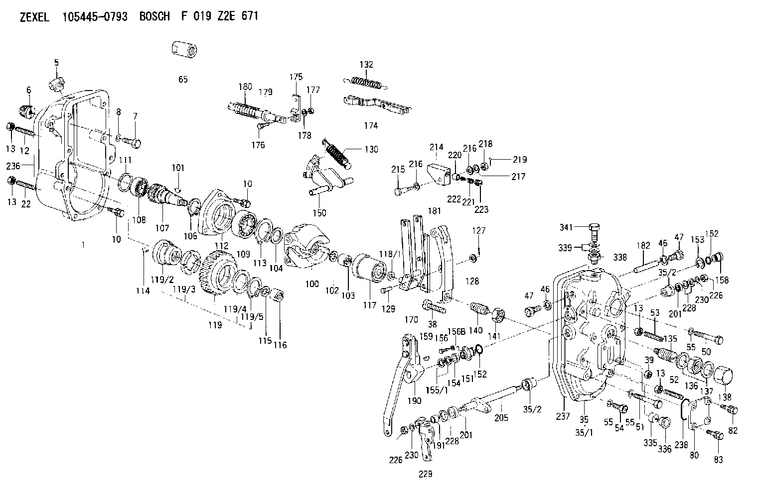
| 1. | [1] | 154003-2020 | GOVERNOR HOUSING |
| 5. | [1] | 154007-3400 | CAPSULE |
| 6. | [1] | 154007-0500 | ADAPTOR |
| 7. | [1] | 010038-1840 | BLEEDER SCREW M8P1.25L18 |
| 8. | [1] | 014110-8440 | LOCKING WASHER |
| 10. | [10] | 020018-2840 | BLEEDER SCREW |
| 10. | [10] | 020018-2840 | BLEEDER SCREW |
| 12. | [1] | 154010-9500 | FLAT-HEAD SCREW |
| 13. | [4] | 029241-0020 | UNION NUT |
| 13. | [4] | 029241-0020 | UNION NUT |
| 13. | [4] | 029241-0020 | UNION NUT |
| 13. | [4] | 029241-0020 | UNION NUT |
| 22. | [1] | 154010-9800 | FLAT-HEAD SCREW |
| 35. | [1] | 154522-4320 | GOVERNOR COVER |
| 35/1. | [1] | 154522-4300 | GOVERNOR COVER |
| 35/2. | [2] | 154204-4200 | BUSHING |
| 35/2. | [2] | 154204-4200 | BUSHING |
| 38. | [1] | 154031-3900 | FLAT-HEAD SCREW |
| 39. | [1] | 029201-0160 | UNION NUT |
| 46. | [2] | 026512-1840 | GASKET D17.9&12.2T1.50 |
| 46. | [2] | 026512-1840 | GASKET D17.9&12.2T1.50 |
| 47. | [2] | 154036-2400 | CAPSULE |
| 47. | [2] | 154036-2400 | CAPSULE |
| 50. | [2] | 139008-0300 | BLEEDER SCREW |
| 51. | [4] | 010038-9140 | BLEEDER SCREW M8P1.25L95 |
| 52. | [1] | 154010-9500 | FLAT-HEAD SCREW |
| 53. | [1] | 154010-9700 | FLAT-HEAD SCREW |
| 54. | [3] | 010038-2840 | BLEEDER SCREW |
| 55. | [9] | 014110-8410 | LOCKING WASHER |
| 55. | [9] | 014110-8410 | LOCKING WASHER |
| 55. | [9] | 014110-8410 | LOCKING WASHER |
| 65. | [1] | 154050-1620 | STOPPING DEVICE |
| 80. | [1] | 154060-4200 | COVER |
| 82. | [2] | 029020-6210 | BLEEDER SCREW |
| 83. | [2] | 020006-1640 | BLEEDER SCREW M6P1L16 4T |
| 100. | [1] | 154102-2420 | FLYWEIGHT ASSEMBLY |
| 101. | [1] | 025804-1610 | WOODRUFF KEY |
| 102. | [1] | 029321-4010 | LOCKING WASHER |
| 103. | [1] | 131325-2600 | UNION NUT |
| 104. | [1] | 154120-0200 | PLAIN WASHER |
| 106. | [1] | 016020-2510 | LOCKING WASHER |
| 107. | [1] | 154121-0900 | TOOTHED GEAR |
| 108. | [1] | 016630-2640 | BEARING PLATE |
| 109. | [1] | 028102-5010 | BEARING PLATE |
| 111. | [1] | 029313-2010 | SHIM D39.8&32T1 |
| 111A. | [1] | 029313-2020 | SHIM D39.8&32T0.2 |
| 112. | [1] | 154122-0200 | COVER |
| 113. | [1] | 016110-5210 | LOCKING WASHER |
| 114. | [1] | 025805-1910 | WOODRUFF KEY |
| 115. | [1] | 023641-8410 | LOCKING WASHER |
| 116. | [1] | 154011-2400 | UNION NUT |
| 117. | [1] | 154123-1820 | SLIDING PIECE |
| 118/1. | [0] | 029311-5020 | SHIM D20.5&15T0.05 |
| 118/1. | [0] | 029311-5030 | SHIM D20.5&15T0.1 |
| 118/1. | [0] | 029311-5050 | SHIM D20.5&15T0.2 |
| 118/1. | [0] | 029311-5060 | SHIM D20.5&15T0.4 |
| 118/1. | [0] | 029311-5080 | SHIM D20.5&15T0.5 |
| 118/1. | [0] | 029311-5120 | SHIM D20.5&15T0.3 |
| 119. | [1] | 154130-2320 | TOOTHED GEAR |
| 119/2. | [1] | 154132-0520 | HOLDER |
| 119/3. | [4] | 153251-1000 | DAMPER |
| 119/4. | [1] | 153321-0100 | PLAIN WASHER |
| 119/5. | [1] | 016020-4010 | LOCKING WASHER |
| 127. | [1] | 015325-1590 | SPLIT PIN |
| 128. | [1] | 029310-6040 | SHIM |
| 129. | [1] | 154356-6000 | BEARING PIN |
| 130. | [1] | 154150-9320 | GOVERNOR SPRING |
| 132. | [1] | 154154-2300 | COILED SPRING |
| 135. | [1] | 154158-3020 | HEADLESS SCREW |
| 136. | [1] | 139226-0000 | UNION NUT |
| 137. | [2] | 029332-6030 | GASKET |
| 138. | [1] | 154159-1600 | CAP NUT |
| 140. | [1] | 154187-0120 | HEADLESS SCREW |
| 141. | [1] | 139220-0400 | UNION NUT |
| 150. | [1] | 154200-7620 | SWIVELLING LEVER |
| 151. | [1] | 154204-3200 | BUSHING |
| 152. | [2] | 139718-0200 | O-RING |
| 152. | [2] | 139718-0200 | O-RING |
| 153. | [1] | 016010-2010 | LOCKING WASHER |
| 154. | [1] | 139614-0300 | PACKING RING |
| 155/1. | [0] | 029311-4040 | SHIM D26&14.2T0.3 |
| 155/1. | [0] | 029311-4050 | SHIM D26&14.2T0.4 |
| 155/1. | [0] | 029311-4060 | SHIM D26&14.2T0.5 |
| 155/1. | [0] | 029311-4080 | SHIM D26&14.2T0.1 |
| 156. | [2] | 154372-1800 | BLEEDER SCREW |
| 156B. | [2] | 014110-8440 | LOCKING WASHER |
| 158. | [1] | 154204-2600 | BUSHING |
| 159. | [1] | 025803-1310 | WOODRUFF KEY |
| 170. | [1] | 154217-6020 | FORK LEVER |
| 174. | [1] | 154234-0920 | STRAP |
| 175. | [1] | 154232-0100 | CONNECTOR |
| 176. | [1] | 010006-1840 | BLEEDER SCREW M6P1L18 4T |
| 177. | [1] | 013020-6040 | UNION NUT M6P1H5 |
| 178. | [2] | 154233-0100 | TAB WASHER |
| 179. | [1] | 153400-0200 | SLOTTED WASHER |
| 180. | [1] | 153401-0300 | COILED SPRING |
| 181. | [1] | 154236-8100 | TENSIONING LEVER |
| 182. | [1] | 154237-0300 | BEARING PIN |
| 190. | [1] | 154396-3920 | CONTROL LEVER |
| 191. | [1] | 154376-1300 | BUSHING |
| 201. | [2] | 139614-0300 | PACKING RING |
| 201. | [2] | 139614-0300 | PACKING RING |
| 205. | [1] | 154330-1301 | LEVER SHAFT |
| 214. | [1] | 154333-0200 | CONTROL LEVER |
| 215. | [1] | 154334-0100 | BEARING PIN |
| 216. | [2] | 029301-0030 | PLAIN WASHER |
| 216. | [2] | 029301-0030 | PLAIN WASHER |
| 217. | [1] | 029300-8070 | PLAIN WASHER |
| 218. | [1] | 013020-8020 | UNION NUT M8P1.25H7 |
| 219. | [1] | 025520-1210 | SPLIT PIN |
| 220. | [1] | 154335-0100 | SLOTTED WASHER |
| 221. | [1] | 154336-0100 | COILED SPRING |
| 222. | [1] | 154336-0200 | COILED SPRING |
| 223. | [1] | 154337-0100 | CAPSULE |
| 226. | [2] | 013020-8040 | UNION NUT M8P1.25H7 |
| 226. | [2] | 013020-8040 | UNION NUT M8P1.25H7 |
| 228. | [0] | 139414-0000 | SHIM |
| 228. | [0] | 139414-0000 | SHIM |
| 229. | [1] | 154364-9900 | CONTROL LEVER |
| 230. | [3] | 014110-8410 | LOCKING WASHER |
| 230. | [3] | 014110-8410 | LOCKING WASHER |
| 236. | [1] | 154390-3000 | GASKET |
| 237. | [1] | 154390-3200 | GASKET |
| 238. | [1] | 029635-5010 | O-RING |
| 335. | [1] | 154159-1700 | UNION NUT |
| 336. | [1] | 154356-6100 | CAPSULE |
| 338. | [1] | 131002-3800 | ADAPTOR |
| 339. | [2] | 029341-2140 | GASKET |
| 341. | [1] | 154373-1700 | EYE BOLT |
Cross reference number
Zexel num
Bosch num
Firm num
Name
105445-0793
GOVERNOR
K 14JC MECHANICAL GOVERNOR GOV RSUV(D) GOV
K 14JC MECHANICAL GOVERNOR GOV RSUV(D) GOV
Information:
(1) Gear. If new gear is required, replace camshaft assembly. The heat treatment of the gear is damaged if heated.(2) Diameter of the surfaces (journals) for the camshaft bearings (new) ... 69.850 0.013 mm (2.7500 .0005 in) Bore in front bearing for the camshaft (after assembly) ... 69.969 0.048 mm (2.7547 .0019 in)Bore in the other six bearings for the camshaft (after assembly) ... 69.982 0.061 mm (2.7552 .0024 in)(3) Thickness of thrust plate (new) ... 4.65 0.03 mm (.183 .001 in) End play of the camshaft ... 0.10 to 0.26 mm (.004 to .010 in)(4) Camshaft. (5) Height of camshaft lobes.To find lobe height, use the procedure that follows:A. Measure camshaft lobe height (5).B. Measure base circle (7).C. Subtract base circle (STEP B) from lobe height (STEP A). The difference is actual lobe lift (6).D. Specified camshaft lobe lift (6) is: Camshaft Assemblya. Exhaust lobe ... 10.5 mm (.413 in)b. Inlet lobe ... 10.5 mm (.413 in)Maximum permissible difference between actual lobe lift (STEP C) and specified lobe lift (STEP D) is 0.13 mm (.005 in)Inlet Valve Timing
1. Check the No. 1 inlet valve lash with the engine stopped. The valve lash must be 0.30 to 0.46 mm (.012 to .018 in). If the valve lash is not in this range, adjust the lash to 0.38 mm (.015 in).2. Mark Top Center Position of the crankshaft on the vibration damper or pulley.3. Use a dial indicator to measure the inlet valve movement.4. Rotate the crankshaft in the direction of normal engine rotation. Stop when the inlet valve is 1.91 mm (.075 in) off its seat in the opening sequence.At this point the crankshaft Top Center Position Mark must be ... 5 2 degrees After Top CenterChecking Valve-Camshaft Timing (field procedure)
The following procedure will simplify the checking of the camshaft timing procedures.1. Set the No. 3 inlet bridge adjustment. Refer to SENR6547 (Testing And Adjusting).2. Set the No. 3 inlet valve lash. Refer to SENR6547 (Testing And Adjusting).3. Install the bolt in the flywheel with No. 1 piston at top center.4. Install the dial indicator (magnetic base) to No. 3 inlet bridge.5. Remove the bolt from the flywheel.6. Set the indicator at zero and rotate the engine in the normal direction of operation (counterclockwise as viewed from the flywheel end) until dial travel stops.The correct setting should be ... 14.21 0.25 mm (.560 .010 in)