Information governor
BOSCH
9 420 610 207
9420610207
ZEXEL
105445-0791
1054450791
Rating:
Scheme ###:
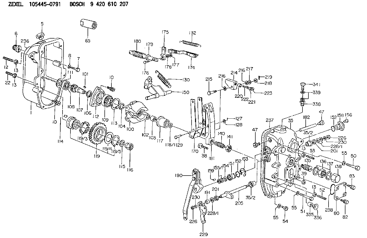
| 1. | [1] | 154003-2020 | GOVERNOR HOUSING |
| 5. | [1] | 154007-3400 | CAPSULE |
| 6. | [1] | 154007-0500 | ADAPTOR |
| 7. | [1] | 010038-1840 | BLEEDER SCREW M8P1.25L18 |
| 8. | [1] | 014110-8440 | LOCKING WASHER |
| 10. | [10] | 020018-2840 | BLEEDER SCREW |
| 10. | [10] | 020018-2840 | BLEEDER SCREW |
| 12. | [1] | 154010-9500 | FLAT-HEAD SCREW |
| 13. | [4] | 029241-0020 | UNION NUT |
| 13. | [4] | 029241-0020 | UNION NUT |
| 13. | [4] | 029241-0020 | UNION NUT |
| 13. | [4] | 029241-0020 | UNION NUT |
| 22. | [1] | 154010-9800 | FLAT-HEAD SCREW |
| 35. | [1] | 154522-2020 | GOVERNOR COVER |
| 35/2. | [2] | 154204-0600 | BUSHING |
| 35/2. | [2] | 154204-0600 | BUSHING |
| 38. | [1] | 154031-3900 | FLAT-HEAD SCREW |
| 39. | [1] | 029201-0160 | UNION NUT |
| 47. | [2] | 154036-0400 | CAPSULE |
| 47. | [2] | 154036-0400 | CAPSULE |
| 50. | [2] | 139008-0300 | BLEEDER SCREW |
| 51. | [4] | 010038-9140 | BLEEDER SCREW M8P1.25L95 |
| 52. | [1] | 154010-9500 | FLAT-HEAD SCREW |
| 53. | [1] | 154010-9700 | FLAT-HEAD SCREW |
| 54. | [3] | 010008-2840 | BLEEDER SCREW |
| 55. | [9] | 014110-8410 | LOCKING WASHER |
| 55. | [9] | 014110-8410 | LOCKING WASHER |
| 55. | [9] | 014110-8410 | LOCKING WASHER |
| 65. | [1] | 154050-1620 | STOPPING DEVICE |
| 80. | [1] | 154060-4200 | COVER |
| 82. | [2] | 029020-6210 | BLEEDER SCREW |
| 83. | [2] | 020006-1640 | BLEEDER SCREW M6P1L16 4T |
| 100. | [1] | 154102-2420 | FLYWEIGHT ASSEMBLY |
| 101. | [1] | 025804-1610 | WOODRUFF KEY |
| 102. | [1] | 029321-4010 | LOCKING WASHER |
| 103. | [1] | 131325-2600 | UNION NUT |
| 104. | [1] | 154120-0200 | PLAIN WASHER |
| 106. | [1] | 016020-2510 | LOCKING WASHER |
| 107. | [1] | 154121-0900 | TOOTHED GEAR |
| 108. | [1] | 016630-2640 | BEARING PLATE |
| 109. | [1] | 028102-5010 | BEARING PLATE |
| 111. | [1] | 029313-2010 | SHIM D39.8&32T1 |
| 111A. | [1] | 029313-2020 | SHIM D39.8&32T0.2 |
| 112. | [1] | 154122-0200 | COVER |
| 113. | [1] | 016110-5210 | LOCKING WASHER |
| 114. | [1] | 025805-1910 | WOODRUFF KEY |
| 115. | [1] | 023641-8410 | LOCKING WASHER |
| 116. | [1] | 154011-2400 | UNION NUT |
| 117. | [1] | 154123-1820 | SLIDING PIECE |
| 118/1. | [0] | 029311-5020 | SHIM D20.5&15T0.05 |
| 118/1. | [0] | 029311-5030 | SHIM D20.5&15T0.1 |
| 118/1. | [0] | 029311-5050 | SHIM D20.5&15T0.2 |
| 118/1. | [0] | 029311-5060 | SHIM D20.5&15T0.4 |
| 118/1. | [0] | 029311-5080 | SHIM D20.5&15T0.5 |
| 118/1. | [0] | 029311-5120 | SHIM D20.5&15T0.3 |
| 119. | [1] | 154130-2320 | TOOTHED GEAR |
| 119/3. | [4] | 153251-1000 | DAMPER |
| 119/4. | [1] | 153321-0100 | PLAIN WASHER |
| 119/5. | [1] | 016020-4010 | LOCKING WASHER |
| 127. | [1] | 015325-1590 | SPLIT PIN |
| 128. | [1] | 029310-6040 | SHIM |
| 129. | [1] | 154356-6000 | BEARING PIN |
| 130. | [1] | 154150-9320 | GOVERNOR SPRING |
| 132. | [1] | 154154-2300 | COILED SPRING |
| 135. | [1] | 154158-3020 | HEADLESS SCREW |
| 136. | [1] | 139226-0000 | UNION NUT |
| 137. | [2] | 029332-6030 | GASKET |
| 138. | [1] | 154159-1600 | CAP NUT |
| 140. | [1] | 154187-0120 | HEADLESS SCREW |
| 141. | [1] | 139220-0400 | UNION NUT |
| 150. | [1] | 154200-6020 | SWIVELLING LEVER |
| 151. | [1] | 154204-3200 | BUSHING |
| 152. | [2] | 139718-0200 | O-RING |
| 152. | [2] | 139718-0200 | O-RING |
| 153. | [1] | 016010-2010 | LOCKING WASHER |
| 154. | [1] | 139614-0300 | PACKING RING |
| 155/1. | [0] | 029311-4040 | SHIM D26&14.2T0.3 |
| 155/1. | [0] | 029311-4050 | SHIM D26&14.2T0.4 |
| 155/1. | [0] | 029311-4060 | SHIM D26&14.2T0.5 |
| 155/1. | [0] | 029311-4080 | SHIM D26&14.2T0.1 |
| 156. | [2] | 154372-1800 | BLEEDER SCREW |
| 158. | [1] | 154204-2600 | BUSHING |
| 159. | [1] | 025803-1310 | WOODRUFF KEY |
| 170. | [1] | 154217-6020 | FORK LEVER |
| 174. | [1] | 154234-0920 | STRAP |
| 175. | [1] | 154232-0100 | CONNECTOR |
| 176. | [1] | 010006-1840 | BLEEDER SCREW M6P1L18 4T |
| 177. | [1] | 013020-6040 | UNION NUT M6P1H5 |
| 178. | [2] | 154233-0100 | TAB WASHER |
| 179. | [1] | 153400-0200 | SLOTTED WASHER |
| 180. | [1] | 153401-0300 | COILED SPRING |
| 181. | [1] | 154236-8100 | TENSIONING LEVER |
| 182. | [1] | 154237-0300 | BEARING PIN |
| 190. | [1] | 154347-3220 | CONTROL LEVER |
| 191. | [1] | 154351-0600 | BUSHING |
| 201. | [2] | 139614-0400 | PACKING RING |
| 201. | [2] | 139614-0400 | PACKING RING |
| 205. | [1] | 154330-1301 | LEVER SHAFT |
| 214. | [1] | 154333-0200 | CONTROL LEVER |
| 215. | [1] | 154334-0100 | BEARING PIN |
| 216. | [2] | 029301-0030 | PLAIN WASHER |
| 216. | [2] | 029301-0030 | PLAIN WASHER |
| 217. | [1] | 029300-8070 | PLAIN WASHER |
| 218. | [1] | 013020-8020 | UNION NUT M8P1.25H7 |
| 219. | [1] | 025520-1210 | SPLIT PIN |
| 220. | [1] | 154335-0100 | SLOTTED WASHER |
| 221. | [1] | 154336-0100 | COILED SPRING |
| 222. | [1] | 154336-0200 | COILED SPRING |
| 223. | [1] | 154337-0100 | CAPSULE |
| 226. | [2] | 013020-8040 | UNION NUT M8P1.25H7 |
| 226. | [2] | 013020-8040 | UNION NUT M8P1.25H7 |
| 228/1. | [0] | 029311-4010 | SHIM D19.5&14.2T0.30 |
| 228/1. | [0] | 029311-4020 | SHIM D19.5&14.2T0.40 |
| 228/1. | [0] | 029311-4020 | SHIM D19.5&14.2T0.40 |
| 228/1. | [0] | 029311-4020 | SHIM D19.5&14.2T0.40 |
| 228/1. | [0] | 029311-4030 | SHIM D19.5&14.2T0.50 |
| 229. | [1] | 154364-9900 | CONTROL LEVER |
| 230. | [3] | 014110-8410 | LOCKING WASHER |
| 230. | [3] | 014110-8410 | LOCKING WASHER |
| 236. | [1] | 154390-3000 | GASKET |
| 237. | [1] | 154390-3200 | GASKET |
| 238. | [1] | 029635-5010 | O-RING |
| 335. | [1] | 154159-1700 | UNION NUT |
| 336. | [1] | 154356-6100 | CAPSULE |
| 338. | [1] | 131002-3800 | ADAPTOR |
| 339. | [2] | 029341-2140 | GASKET |
| 341. | [1] | 154373-1700 | EYE BOLT |
Cross reference number
Zexel num
Bosch num
Firm num
Name
Information:
The troubleshooting chart provides a definite sequence to be followed for a logical procedure to determine the frequency and amplitude of vibration so that the source of the vibration can be located and corrected.1. The customer must be asked questions to determine whether his complaint is valid, or whether his diagnosis of the actual problem is correct.Some of the questions that must be asked are as follows:a. What components are vibrating?b. In what speed range does this vibration become excessive?c. Does clutch operation affect the vibration?d. What is the history of the problem?2. Run the engine through the idle speed range and note all vibrating components. Look for any loose or broken mounts, brackets, and fasteners. Repair and tighten any fixtures.3. Check idle speed range with clutch disengaged. If vibrations subside, there is a balance problem with the clutch disc. The clutch disc must be repaired or replaced.4. Further analysis requires the use of a vibration instrument. Any instrument which can accurately measure the displacement of the vibration (usually in mils-inch/1000) and the frequency (cycles per second) will be sufficient. A vibration instrument such as the IRD Mechanalysis Model 320 or an equivalent instrument can be used to analyze vibration.5. Measure vibration of cab components which have the objectionable vibration.Run engine slowly through the speed range and measure vibration with the instrument filter OUT. When peak amplitudes are found, run the engine at the speeds they occur and with the instrument filter IN, find the frequency of the vibration.If the frequency of vibration is 1/2 times of engine rpm (1/2 order), the vibration is caused by a cylinder misfiring. This must be corrected before further vibration analysis is made.If the frequency of vibration is 3 times engine rpm, no corrective action can be taken on the engine because this is the firing frequency of the 3306 engine. The problem is in the cab or chassis resonance.If frequency is some order other than 1/2 or 3rd, then further measurements must be made on the engine.6. Measurements taken on the engine must be made perpendicular to the crankshaft at the front and, rear of the engine in vertical and horizontal directions.7. Record all vibrations over 4.0 mils and the engine rpm at which it occurs (100 rpm intervals are sufficient) with instrument filter OUT. Note any sudden increase and decrease in amplitudes. These occur in resonant speed ranges.If no amplitudes exceed 4.0 mils, the engine is within Caterpillar Specifications.If amplitudes exceed 4.0 mils, the vibrations must be measured with the instrument filter IN to obtain the frequency of the vibrations.8. Run the engine at high idle. With the instrument filter IN, check the frequency range and record any amplitudes over 4.0 mils and the corresponding frequency. Analysis of vibrations for the possible causes is done by identifying the frequency of the vibration and where on the engine it is the greatest magnitude. Make reference to Special Instruction, Troubleshooting Engine Vibration In Vehicular Equipment, SEHS7914 for additional information for troubleshooting vibration complaints.