Information governor
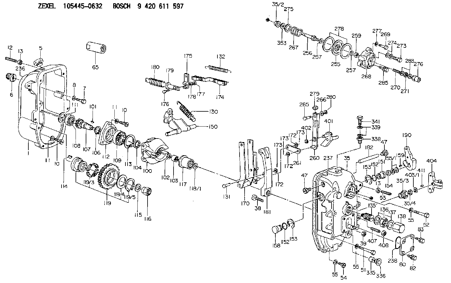
BOSCH
9 420 611 597
9420611597
ZEXEL
105445-0632
1054450632
Rating:
Scheme ###:
| 1. | [1] | 154003-1520 | GOVERNOR HOUSING |
| 5. | [1] | 154007-3400 | CAPSULE |
| 6. | [1] | 154007-0500 | ADAPTOR |
| 7. | [1] | 010038-1840 | BLEEDER SCREW M8P1.25L18 |
| 8. | [1] | 014110-8440 | LOCKING WASHER |
| 10. | [10] | 010038-2840 | BLEEDER SCREW |
| 10. | [10] | 010038-2840 | BLEEDER SCREW |
| 11. | [10] | 014110-8440 | LOCKING WASHER |
| 11. | [10] | 014110-8440 | LOCKING WASHER |
| 12. | [1] | 154010-9500 | FLAT-HEAD SCREW |
| 13. | [2] | 029241-0020 | UNION NUT |
| 13. | [2] | 029241-0020 | UNION NUT |
| 35. | [1] | 154522-3220 | GOVERNOR COVER |
| 35/2. | [1] | 154412-8500 | BUSHING |
| 35/3. | [1] | 154204-2800 | BUSHING |
| 35/4. | [1] | 029621-0080 | PACKING RING |
| 38. | [1] | 154031-3900 | FLAT-HEAD SCREW |
| 39. | [1] | 029201-0160 | UNION NUT |
| 47. | [2] | 154036-0400 | CAPSULE |
| 47. | [2] | 154036-0400 | CAPSULE |
| 51. | [4] | 010038-9140 | BLEEDER SCREW M8P1.25L95 |
| 52. | [2] | 139008-0500 | BLEEDER SCREW |
| 53. | [1] | 154010-9500 | FLAT-HEAD SCREW |
| 54. | [2] | 010038-2840 | BLEEDER SCREW |
| 55. | [8] | 014110-8410 | LOCKING WASHER |
| 55. | [8] | 014110-8410 | LOCKING WASHER |
| 55. | [8] | 014110-8410 | LOCKING WASHER |
| 65. | [1] | 154050-1620 | STOPPING DEVICE |
| 80. | [1] | 154060-4200 | COVER |
| 82. | [2] | 029020-6210 | BLEEDER SCREW |
| 83. | [2] | 020006-1640 | BLEEDER SCREW M6P1L16 4T |
| 100. | [1] | 154102-2420 | FLYWEIGHT ASSEMBLY |
| 101. | [1] | 025804-1610 | WOODRUFF KEY |
| 102. | [1] | 029321-4010 | LOCKING WASHER |
| 103. | [1] | 131325-2600 | UNION NUT |
| 104. | [1] | 154120-0200 | PLAIN WASHER |
| 106. | [1] | 016020-2510 | LOCKING WASHER |
| 107. | [1] | 154121-0900 | TOOTHED GEAR |
| 108. | [1] | 016630-2640 | BEARING PLATE |
| 109. | [1] | 028102-5010 | BEARING PLATE |
| 111. | [1] | 029313-2010 | SHIM D39.8&32T1 |
| 111A. | [1] | 029313-2020 | SHIM D39.8&32T0.2 |
| 112. | [1] | 154122-0200 | COVER |
| 113. | [1] | 016110-5210 | LOCKING WASHER |
| 114. | [1] | 025805-1910 | WOODRUFF KEY |
| 115. | [1] | 023641-8410 | LOCKING WASHER |
| 116. | [1] | 154011-2400 | UNION NUT |
| 117. | [1] | 154123-1820 | SLIDING PIECE |
| 118/1. | [0] | 029311-5020 | SHIM D20.5&15T0.05 |
| 118/1. | [0] | 029311-5030 | SHIM D20.5&15T0.1 |
| 118/1. | [0] | 029311-5050 | SHIM D20.5&15T0.2 |
| 118/1. | [0] | 029311-5060 | SHIM D20.5&15T0.4 |
| 118/1. | [0] | 029311-5080 | SHIM D20.5&15T0.5 |
| 118/1. | [0] | 029311-5120 | SHIM D20.5&15T0.3 |
| 119. | [1] | 154130-2320 | TOOTHED GEAR |
| 119/2. | [1] | 154132-0520 | HOLDER |
| 119/3. | [4] | 153251-1000 | DAMPER |
| 119/4. | [1] | 153321-0100 | PLAIN WASHER |
| 119/5. | [1] | 016020-4010 | LOCKING WASHER |
| 130. | [1] | 154150-9520 | GOVERNOR SPRING |
| 131. | [1] | 154356-6000 | BEARING PIN |
| 132. | [1] | 154154-2300 | COILED SPRING |
| 135. | [1] | 154158-2620 | HEADLESS SCREW |
| 136. | [1] | 139226-0000 | UNION NUT |
| 137. | [2] | 029332-6030 | GASKET |
| 138. | [1] | 154159-1600 | CAP NUT |
| 150. | [1] | 154200-6120 | SWIVELLING LEVER |
| 151. | [1] | 154204-2500 | BUSHING |
| 152. | [2] | 029631-8020 | O-RING |
| 152. | [2] | 029631-8020 | O-RING |
| 152. | [2] | 029631-8020 | O-RING |
| 153. | [2] | 016010-2010 | LOCKING WASHER |
| 154. | [1] | 139614-0100 | PACKING RING |
| 155/1. | [0] | 029311-4040 | SHIM D26&14.2T0.3 |
| 155/1. | [0] | 029311-4050 | SHIM D26&14.2T0.4 |
| 155/1. | [0] | 029311-4060 | SHIM D26&14.2T0.5 |
| 155/1. | [0] | 029311-4080 | SHIM D26&14.2T0.1 |
| 158. | [1] | 154204-2600 | BUSHING |
| 159. | [1] | 025803-1310 | WOODRUFF KEY |
| 170. | [1] | 154217-5820 | FORK LEVER |
| 172. | [3] | 029310-6040 | SHIM |
| 172. | [3] | 029310-6040 | SHIM |
| 172. | [3] | 029310-6040 | SHIM |
| 173. | [3] | 015325-1590 | SPLIT PIN |
| 173. | [3] | 015325-1590 | SPLIT PIN |
| 173. | [3] | 015325-1590 | SPLIT PIN |
| 174. | [1] | 154234-0920 | STRAP |
| 175. | [1] | 154232-0100 | CONNECTOR |
| 176. | [1] | 010006-1840 | BLEEDER SCREW M6P1L18 4T |
| 177. | [1] | 013020-6040 | UNION NUT M6P1H5 |
| 178. | [2] | 154233-0100 | TAB WASHER |
| 179. | [1] | 153400-0200 | SLOTTED WASHER |
| 180. | [1] | 153401-0300 | COILED SPRING |
| 181. | [1] | 154236-8100 | TENSIONING LEVER |
| 182. | [1] | 154237-0300 | BEARING PIN |
| 190. | [1] | 154347-8020 | CONTROL LEVER |
| 236. | [1] | 154390-3000 | GASKET |
| 237. | [1] | 154390-3300 | GASKET |
| 238. | [1] | 029635-5010 | O-RING |
| 255. | [1] | 154400-7420 | DIAPHRAGM |
| 256. | [1] | 154401-3800 | STOP PIN |
| 257. | [2] | 029330-8050 | GASKET |
| 257. | [2] | 029330-8050 | GASKET |
| 259. | [1] | 154372-7200 | HEXAGON NUT |
| 260. | [1] | 154401-3921 | STRAP |
| 261. | [1] | 154401-4320 | STRAP |
| 265. | [1] | 154222-8200 | BEARING PIN |
| 266. | [1] | 029310-5280 | SHIM D10.5&5T0.5 |
| 267. | [1] | 154402-5800 | COILED SPRING |
| 268. | [1] | 154404-5000 | COVER |
| 269. | [2] | 020106-2240 | BLEEDER SCREW |
| 270. | [1] | 154404-1100 | FLAT-HEAD SCREW |
| 271. | [1] | 013030-6040 | UNION NUT M6P1H3.6 |
| 273. | [1] | 029731-0120 | EYE BOLT |
| 274. | [2] | 029341-0110 | GASKET |
| 275. | [0] | 029312-0180 | SHIM D25.5&20T0.5 |
| 275B. | [0] | 029312-0210 | SHIM D25.5&20T0.2 |
| 276. | [1] | 154035-1600 | CAP NUT |
| 277. | [1] | 029320-6010 | LOCKING WASHER |
| 278. | [2] | 154413-2600 | GASKET |
| 279. | [1] | 154223-0100 | SLIDING PIECE |
| 280. | [1] | 026110-0510 | LOCKING WASHER |
| 283. | [2] | 026506-1040 | GASKET D9.9&6.2T1 |
| 285. | [1] | 029010-6310 | BLEEDER SCREW |
| 335. | [1] | 154159-1700 | UNION NUT |
| 336. | [1] | 154356-6100 | CAPSULE |
| 338. | [1] | 131002-3800 | ADAPTOR |
| 339. | [2] | 029341-2140 | GASKET |
| 341. | [1] | 139812-2300 | EYE BOLT |
| 353. | [7] | 029311-0470 | SHIM |
| 401. | [1] | 154326-7820 | CONTROL LEVER |
| 402. | [1] | 016010-0840 | LOCKING WASHER |
| 403/1. | [0] | 029311-0640 | SHIM D26.0&10.2T0.95 |
| 403/1. | [0] | 029311-0650 | SHIM D26.0&10.2T0.20 |
| 403/1. | [0] | 029311-0660 | SHIM D26.0&10.2T0.25 |
| 403/1. | [0] | 029311-0670 | SHIM D26.0&10.2T0.30 |
| 403/1. | [0] | 029311-0680 | SHIM D26.0&10.2T0.35 |
| 403/1. | [0] | 029311-0690 | SHIM D26.0&10.2T0.40 |
| 403/1. | [0] | 029311-0700 | SHIM D26.0&10.2T0.50 |
| 403/1. | [0] | 139410-1400 | SHIM D26&10.2T0.7 |
| 403/1. | [0] | 139410-1500 | SHIM D26&10.2T0.9 |
| 403/1. | [0] | 139410-1600 | SHIM D26&10.2T0.8 |
| 403/1. | [0] | 139410-2700 | SHIM D26&10.2T0.6 |
| 404. | [1] | 154366-4120 | CONTROL LEVER |
| 407. | [2] | 154010-2300 | FLAT-HEAD SCREW |
| 408. | [2] | 029240-8000 | UNION NUT |
| 411. | [1] | 025802-1010 | WOODRUFF KEY |
Include in #1:
103860-0031
as GOVERNOR
Cross reference number
Zexel num
Bosch num
Firm num
Name
105445-0632
GOVERNOR
K 14JC MECHANICAL GOVERNOR GOV RSUV(D) GOV
K 14JC MECHANICAL GOVERNOR GOV RSUV(D) GOV
Information:
Start By:a. remove cylinder head assemblyb. remove engine balancer group (3114 Engines)c. remove oil pump (3116 Engines)d. remove piston cooling tubes 1. Check the connecting rods and caps for their identification and location in the engine. The connecting rods are to be marked (only by etching) with the number of the cylinder in which they are used. Rods and caps are to be marked on the same side of the rod in relation to the bearing retainer notch.2. Remove rod cap nuts (1) and rod bearing cap (2) from the connecting rod. Remove the lower half of the bearing from the rod bearing cap.
To protect the crankshaft from the threaded portion of the connecting rod bolts, cut short pieces of rubber hose, and install them over the threaded portion of the bolts as shown in Photo C20235P1.
3. Carefully remove the piston and connecting rod from the cylinder block. Remove the upper half of the bearing from the connecting rod.4. Remove the remainder of the pistons and connecting rods as in Steps 1 through 3. The following steps are for the installation of the pistons and connecting rod assemblies. 5. Position the piston ring end gaps 120 degrees apart. Install Tool (A) on the piston as shown.6. Be sure the short pieces of rubber hose are installed on the connecting rod bolts. Install the connecting rod and piston group with the rod forging part number facing to the rear of the engine. The rear of the engine is the flywheel end. Thoroughly lubricate the piston crown, piston skirt and the cylinder bore with clean engine oil just prior to installation of the piston group in the cylinder block.7. With the number one crankshaft throw at bottom center, carefully install the piston and connecting rod assembly in the cylinder block. 8. Put the connecting rod in alignment with the crankshaft. Using a rubber mallet, tap the piston into the cylinder bore until Tool (A) comes off of the piston.9. Before the connecting rod comes in contact with the crankshaft, install the upper half of the rod bearing. Be sure the bearing tab engages with the groove in the connecting rod.10. Apply clean engine oil on the upper rod bearing. Continue tapping the piston down, guiding the connecting rod onto the crankshaft.11. Position the lower half of the rod bearing in the corresponding numbered rod bearing cap. Be sure the bearing tab engages with the groove in the rod bearing cap.13. Put clean engine oil on the lower rod bearing surface. Install the rod bearing cap on the connecting rod with the number on the bearing cap on the same side and same number as on the connecting rod.14. Tighten the connecting rod bolts as follows: a. Put clean engine oil on the bolt threads, and all surfaces that make contact between the bolts and cap.b. Tighten