Information governor
BOSCH
F 019 Z1F 960
f019z1f960
ZEXEL
105445-0571
1054450571
Rating:
Scheme ###:
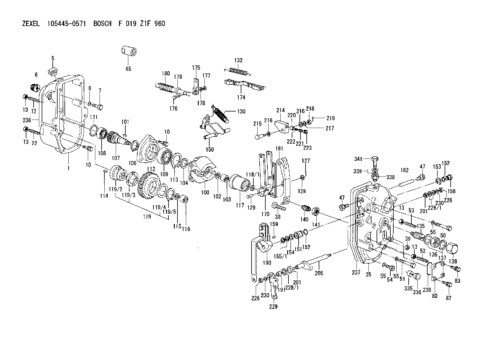
| 1. | [1] | 154003-1520 | GOVERNOR HOUSING |
| 5. | [1] | 154007-3400 | CAPSULE |
| 6. | [1] | 154007-0500 | ADAPTOR |
| 7. | [1] | 010038-1840 | BLEEDER SCREW M8P1.25L18 |
| 8. | [1] | 014110-8440 | LOCKING WASHER |
| 10. | [10] | 020018-2840 | BLEEDER SCREW |
| 10. | [10] | 020018-2840 | BLEEDER SCREW |
| 12. | [1] | 154010-9500 | FLAT-HEAD SCREW |
| 13. | [4] | 029241-0020 | UNION NUT |
| 13. | [4] | 029241-0020 | UNION NUT |
| 13. | [4] | 029241-0020 | UNION NUT |
| 13. | [4] | 029241-0020 | UNION NUT |
| 22. | [1] | 154010-9800 | FLAT-HEAD SCREW |
| 35. | [1] | 154522-0620 | GOVERNOR COVER |
| 38. | [1] | 154031-3900 | FLAT-HEAD SCREW |
| 39. | [1] | 029201-0160 | UNION NUT |
| 47. | [2] | 154036-0400 | CAPSULE |
| 47. | [2] | 154036-0400 | CAPSULE |
| 50. | [2] | 139008-0300 | BLEEDER SCREW |
| 51. | [4] | 010038-9140 | BLEEDER SCREW M8P1.25L95 |
| 52. | [1] | 154010-9500 | FLAT-HEAD SCREW |
| 53. | [1] | 154010-9500 | FLAT-HEAD SCREW |
| 54. | [2] | 010038-2840 | BLEEDER SCREW |
| 55. | [8] | 014110-8440 | LOCKING WASHER |
| 55. | [8] | 014110-8440 | LOCKING WASHER |
| 55. | [8] | 014110-8440 | LOCKING WASHER |
| 65. | [1] | 154050-1620 | STOPPING DEVICE |
| 80. | [1] | 154060-4200 | COVER |
| 82. | [2] | 029020-6210 | BLEEDER SCREW |
| 83. | [2] | 020006-1640 | BLEEDER SCREW M6P1L16 4T |
| 100. | [1] | 154102-2420 | FLYWEIGHT ASSEMBLY |
| 101. | [1] | 025804-1610 | WOODRUFF KEY |
| 102. | [1] | 029321-4010 | LOCKING WASHER |
| 103. | [1] | 131325-2600 | UNION NUT |
| 104. | [1] | 154120-0200 | PLAIN WASHER |
| 106. | [1] | 016020-2510 | LOCKING WASHER |
| 107. | [1] | 154121-0900 | TOOTHED GEAR |
| 108. | [1] | 016630-2640 | BEARING PLATE |
| 109. | [1] | 028102-5010 | BEARING PLATE |
| 111. | [1] | 029313-2010 | SHIM D39.8&32T1 |
| 111A. | [1] | 029313-2020 | SHIM D39.8&32T0.2 |
| 112. | [1] | 154122-0200 | COVER |
| 113. | [1] | 016110-5210 | LOCKING WASHER |
| 114. | [1] | 025805-1910 | WOODRUFF KEY |
| 115. | [1] | 023641-8410 | LOCKING WASHER |
| 116. | [1] | 154011-2400 | UNION NUT |
| 117. | [1] | 154123-1820 | SLIDING PIECE |
| 118/1. | [0] | 029311-5020 | SHIM D20.5&15T0.05 |
| 118/1. | [0] | 029311-5030 | SHIM D20.5&15T0.1 |
| 118/1. | [0] | 029311-5050 | SHIM D20.5&15T0.2 |
| 118/1. | [0] | 029311-5060 | SHIM D20.5&15T0.4 |
| 118/1. | [0] | 029311-5080 | SHIM D20.5&15T0.5 |
| 118/1. | [0] | 029311-5120 | SHIM D20.5&15T0.3 |
| 119. | [1] | 154130-2320 | TOOTHED GEAR |
| 119/2. | [1] | 154132-0520 | HOLDER |
| 119/3. | [4] | 153251-1000 | DAMPER |
| 119/4. | [1] | 153321-0100 | PLAIN WASHER |
| 119/5. | [1] | 016020-4010 | LOCKING WASHER |
| 127. | [1] | 015325-1590 | SPLIT PIN |
| 128. | [1] | 029310-6040 | SHIM |
| 129. | [1] | 154356-6000 | BEARING PIN |
| 130. | [1] | 154150-9520 | GOVERNOR SPRING |
| 132. | [1] | 154154-2300 | COILED SPRING |
| 135. | [1] | 154158-2620 | HEADLESS SCREW |
| 136. | [1] | 139226-0000 | UNION NUT |
| 137. | [2] | 029332-6030 | GASKET |
| 138. | [1] | 154159-1600 | CAP NUT |
| 140. | [1] | 154187-0021 | HEADLESS SCREW |
| 141. | [1] | 139220-0400 | UNION NUT |
| 150. | [1] | 154200-6020 | SWIVELLING LEVER |
| 151. | [1] | 154204-2500 | BUSHING |
| 152. | [2] | 029631-8020 | O-RING |
| 152. | [2] | 029631-8020 | O-RING |
| 153. | [2] | 016010-2010 | LOCKING WASHER |
| 154. | [1] | 139614-0100 | PACKING RING |
| 155/1. | [0] | 029311-4040 | SHIM D26&14.2T0.3 |
| 155/1. | [0] | 029311-4050 | SHIM D26&14.2T0.4 |
| 155/1. | [0] | 029311-4060 | SHIM D26&14.2T0.5 |
| 155/1. | [0] | 029311-4080 | SHIM D26&14.2T0.1 |
| 158. | [1] | 154204-2600 | BUSHING |
| 159. | [1] | 025803-1310 | WOODRUFF KEY |
| 170. | [1] | 154217-6020 | FORK LEVER |
| 174. | [1] | 154234-0920 | STRAP |
| 175. | [1] | 154232-0100 | CONNECTOR |
| 176. | [1] | 010006-1840 | BLEEDER SCREW M6P1L18 4T |
| 177. | [1] | 013020-6040 | UNION NUT M6P1H5 |
| 178. | [2] | 154233-0100 | TAB WASHER |
| 179. | [1] | 153400-0200 | SLOTTED WASHER |
| 180. | [1] | 153401-0300 | COILED SPRING |
| 181. | [1] | 154236-8100 | TENSIONING LEVER |
| 182. | [1] | 154237-0300 | BEARING PIN |
| 190. | [1] | 154347-3220 | CONTROL LEVER |
| 191. | [1] | 154351-0600 | BUSHING |
| 201. | [2] | 029621-4000 | PACKING RING |
| 201. | [2] | 029621-4000 | PACKING RING |
| 205. | [1] | 154330-1301 | LEVER SHAFT |
| 214. | [1] | 154333-0200 | CONTROL LEVER |
| 215. | [1] | 154334-0100 | BEARING PIN |
| 216. | [2] | 029301-0030 | PLAIN WASHER |
| 216. | [2] | 029301-0030 | PLAIN WASHER |
| 217. | [1] | 029300-8070 | PLAIN WASHER |
| 218. | [1] | 013020-8020 | UNION NUT M8P1.25H7 |
| 219. | [1] | 025520-1210 | SPLIT PIN |
| 220. | [1] | 154335-0100 | SLOTTED WASHER |
| 221. | [1] | 154336-0100 | COILED SPRING |
| 222. | [1] | 154336-0200 | COILED SPRING |
| 223. | [1] | 154337-0100 | CAPSULE |
| 226. | [2] | 013020-8040 | UNION NUT M8P1.25H7 |
| 226. | [2] | 013020-8040 | UNION NUT M8P1.25H7 |
| 228/1. | [0] | 029311-4040 | SHIM D26&14.2T0.3 |
| 228/1. | [0] | 029311-4050 | SHIM D26&14.2T0.4 |
| 228/1. | [0] | 029311-4050 | SHIM D26&14.2T0.4 |
| 228/1. | [0] | 029311-4060 | SHIM D26&14.2T0.5 |
| 228/1. | [0] | 029311-4080 | SHIM D26&14.2T0.1 |
| 229. | [1] | 154364-9900 | CONTROL LEVER |
| 230. | [3] | 014110-8440 | LOCKING WASHER |
| 230. | [3] | 014110-8440 | LOCKING WASHER |
| 236. | [1] | 154390-3000 | GASKET |
| 237. | [1] | 154390-3300 | GASKET |
| 238. | [1] | 029635-5010 | O-RING |
| 335. | [1] | 154159-1700 | UNION NUT |
| 336. | [1] | 154356-6100 | CAPSULE |
| 338. | [1] | 131002-3800 | ADAPTOR |
| 339. | [2] | 029341-2140 | GASKET |
| 341. | [1] | 139812-2300 | EYE BOLT |
Include in #1:
103662-2822
as GOVERNOR
Cross reference number
Zexel num
Bosch num
Firm num
Name
Information:
1. Loosen the tension on water pump drive V-belt (1), and remove it from the engine. Remove eight bolts (2) and damper (3) from the crankshaft pulley. 2. Remove four bolts (4), the washer and crankshaft pulley (5) from the end of the crankshaft. 3. Carefully make three evenly spaced holes in the crankshaft front seal with a hammer and sharp punch. Use Tool (A) to remove crankshaft front seal (1). Do not damage the flange of the crankshaft during seal removal. The following steps are for the installation of the vibration damper, crankshaft pulley and crankshaft front seal.4. Be sure the flange of the crankshaft is thoroughly clean prior to installing the crankshaft front seal and the crankshaft pulley. 5. With the shipping sleeve in position, install the crankshaft front seal using Tool (B). The distance between the front face of the crankshaft front seal and the front face of the front housing must be 2.5 0.5 mm (.10 .02 in) after seal installation. See the topic "Crankshaft Seals" in the 3114 & 3116 Diesel Truck Engines Specifications module, Form No. SENR6436 for further details.6. Remove the shipping sleeve from the crankshaft front seal. Apply clean engine oil to the surface of the crankshaft pulley that makes contact with the crankshaft front seal.7. Put crankshaft pulley (5) in position on the crankshaft, and install the washer and four bolts (4) that hold it. Tighten the bolts to a torque of 190 30 N m (140 22 lb ft).8. Install water pump drive V-belt (1).9. Adjust the tension of water pump drive V-belt (1). See the topic "Alternator And Fan Drive Belts, Inspect/Adjust/Replace" in the 3114 & 3116 ATAAC Diesel Truck Engine Operation & Maintenance Manual, Form No. SEBU6723. Also, refer to the "Belt Tension Chart" in the 3114 & 3116 Diesel Truck Engines Specifications module, Form No. SENR6436.