Information governor
BOSCH
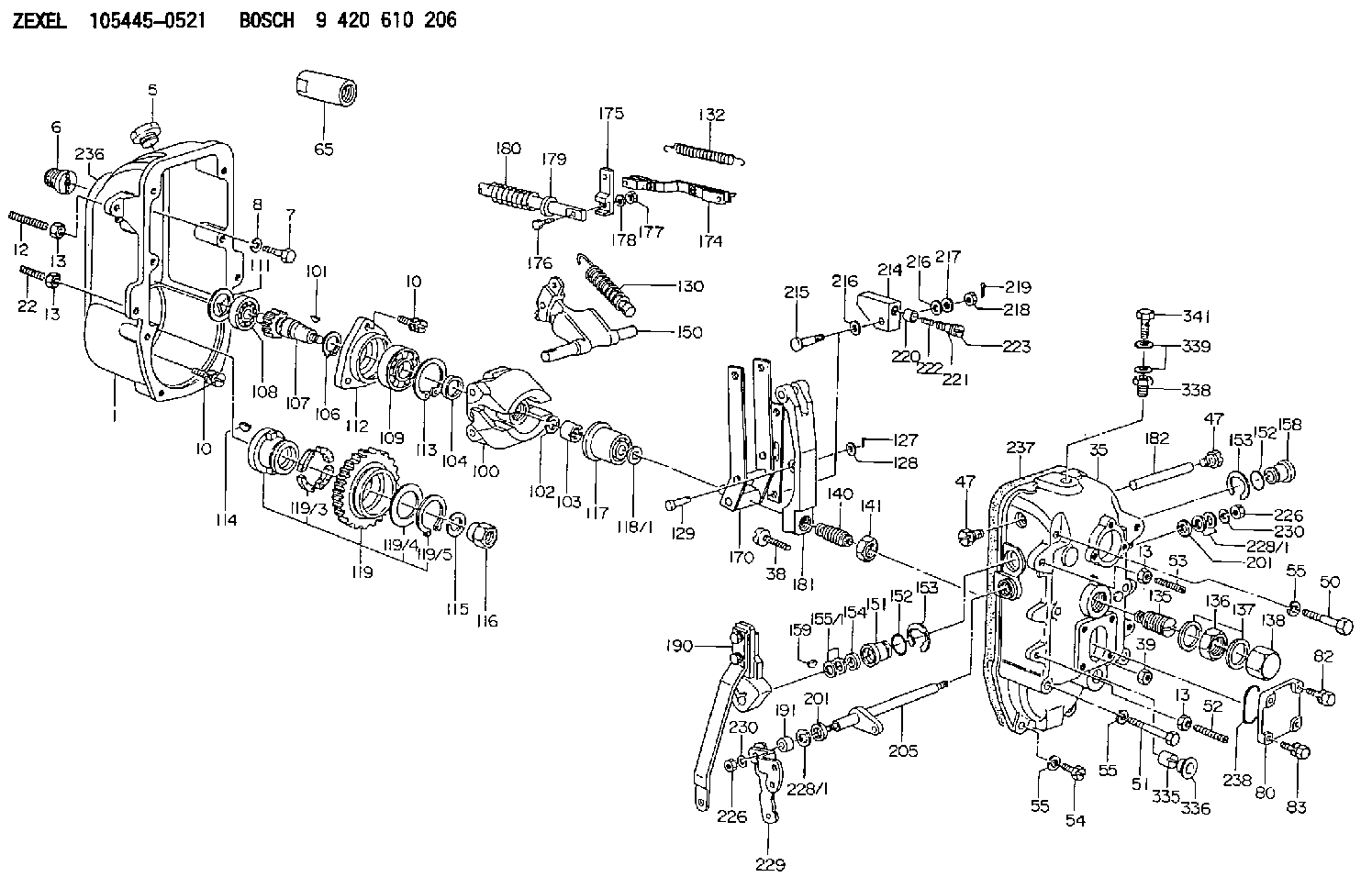
9 420 610 206
9420610206
ZEXEL
105445-0521
1054450521
Rating:
Scheme ###:
| 1. | [1] | 154003-1520 | GOVERNOR HOUSING |
| 5. | [1] | 154007-3400 | CAPSULE |
| 6. | [1] | 154007-0500 | ADAPTOR |
| 7. | [1] | 010038-1840 | BLEEDER SCREW M8P1.25L18 |
| 8. | [1] | 014110-8440 | LOCKING WASHER |
| 10. | [10] | 020018-2840 | BLEEDER SCREW |
| 10. | [10] | 020018-2840 | BLEEDER SCREW |
| 12. | [1] | 154010-9500 | FLAT-HEAD SCREW |
| 13. | [4] | 029241-0020 | UNION NUT |
| 13. | [4] | 029241-0020 | UNION NUT |
| 13. | [4] | 029241-0020 | UNION NUT |
| 13. | [4] | 029241-0020 | UNION NUT |
| 22. | [1] | 154010-9800 | FLAT-HEAD SCREW |
| 35. | [1] | 154522-0620 | GOVERNOR COVER |
| 38. | [1] | 154031-3900 | FLAT-HEAD SCREW |
| 39. | [1] | 029201-0160 | UNION NUT |
| 47. | [2] | 154036-0400 | CAPSULE |
| 47. | [2] | 154036-0400 | CAPSULE |
| 50. | [2] | 139008-0300 | BLEEDER SCREW |
| 51. | [4] | 010038-9140 | BLEEDER SCREW M8P1.25L95 |
| 52. | [1] | 154010-9500 | FLAT-HEAD SCREW |
| 53. | [1] | 154010-9700 | FLAT-HEAD SCREW |
| 54. | [2] | 010038-2840 | BLEEDER SCREW |
| 55. | [8] | 014110-8410 | LOCKING WASHER |
| 55. | [8] | 014110-8410 | LOCKING WASHER |
| 55. | [8] | 014110-8410 | LOCKING WASHER |
| 65. | [1] | 154050-1620 | STOPPING DEVICE |
| 80. | [1] | 154060-4200 | COVER |
| 82. | [2] | 029020-6210 | BLEEDER SCREW |
| 83. | [2] | 020006-1640 | BLEEDER SCREW M6P1L16 4T |
| 100. | [1] | 154102-2420 | FLYWEIGHT ASSEMBLY |
| 101. | [1] | 025804-1610 | WOODRUFF KEY |
| 102. | [1] | 029321-4010 | LOCKING WASHER |
| 103. | [1] | 131325-2600 | UNION NUT |
| 104. | [1] | 154120-0200 | PLAIN WASHER |
| 106. | [1] | 016020-2510 | LOCKING WASHER |
| 107. | [1] | 154121-0900 | TOOTHED GEAR |
| 108. | [1] | 016630-2640 | BEARING PLATE |
| 109. | [1] | 028102-5010 | BEARING PLATE |
| 111. | [1] | 029313-2010 | SHIM D39.8&32T1 |
| 111A. | [1] | 029313-2020 | SHIM D39.8&32T0.2 |
| 112. | [1] | 154122-0200 | COVER |
| 113. | [1] | 016110-5210 | LOCKING WASHER |
| 114. | [1] | 025805-1910 | WOODRUFF KEY |
| 115. | [1] | 023641-8410 | LOCKING WASHER |
| 116. | [1] | 154011-2400 | UNION NUT |
| 117. | [1] | 154123-1820 | SLIDING PIECE |
| 118/1. | [0] | 029311-5020 | SHIM D20.5&15T0.05 |
| 118/1. | [0] | 029311-5030 | SHIM D20.5&15T0.1 |
| 118/1. | [0] | 029311-5050 | SHIM D20.5&15T0.2 |
| 118/1. | [0] | 029311-5060 | SHIM D20.5&15T0.4 |
| 118/1. | [0] | 029311-5080 | SHIM D20.5&15T0.5 |
| 118/1. | [0] | 029311-5120 | SHIM D20.5&15T0.3 |
| 119. | [1] | 154130-2320 | TOOTHED GEAR |
| 119/3. | [4] | 153251-1000 | DAMPER |
| 119/4. | [1] | 153321-0100 | PLAIN WASHER |
| 119/5. | [1] | 016020-4010 | LOCKING WASHER |
| 127. | [1] | 015325-1590 | SPLIT PIN |
| 128. | [1] | 029310-6040 | SHIM |
| 129. | [1] | 154356-6000 | BEARING PIN |
| 130. | [1] | 154150-9320 | GOVERNOR SPRING |
| 132. | [1] | 154154-2300 | COILED SPRING |
| 135. | [1] | 154158-3020 | HEADLESS SCREW |
| 136. | [1] | 139226-0000 | UNION NUT |
| 137. | [2] | 029332-6030 | GASKET |
| 138. | [1] | 154159-1600 | CAP NUT |
| 140. | [1] | 154187-0120 | HEADLESS SCREW |
| 141. | [1] | 139220-0400 | UNION NUT |
| 150. | [1] | 154200-6020 | SWIVELLING LEVER |
| 151. | [1] | 154204-2500 | BUSHING |
| 152. | [2] | 029631-8020 | O-RING |
| 152. | [2] | 029631-8020 | O-RING |
| 153. | [2] | 016010-2010 | LOCKING WASHER |
| 153. | [2] | 016010-2010 | LOCKING WASHER |
| 154. | [1] | 139614-0100 | PACKING RING |
| 155/1. | [0] | 029311-4040 | SHIM D26&14.2T0.3 |
| 155/1. | [0] | 029311-4050 | SHIM D26&14.2T0.4 |
| 155/1. | [0] | 029311-4060 | SHIM D26&14.2T0.5 |
| 155/1. | [0] | 029311-4080 | SHIM D26&14.2T0.1 |
| 158. | [1] | 154204-2600 | BUSHING |
| 159. | [1] | 025803-1310 | WOODRUFF KEY |
| 170. | [1] | 154217-6020 | FORK LEVER |
| 174. | [1] | 154234-0920 | STRAP |
| 175. | [1] | 154232-0100 | CONNECTOR |
| 176. | [1] | 010006-1840 | BLEEDER SCREW M6P1L18 4T |
| 177. | [1] | 013020-6040 | UNION NUT M6P1H5 |
| 178. | [2] | 154233-0100 | TAB WASHER |
| 179. | [1] | 153400-0200 | SLOTTED WASHER |
| 180. | [1] | 153401-0300 | COILED SPRING |
| 181. | [1] | 154236-8100 | TENSIONING LEVER |
| 182. | [1] | 154237-0300 | BEARING PIN |
| 190. | [1] | 154347-3220 | CONTROL LEVER |
| 191. | [1] | 154351-0600 | BUSHING |
| 201. | [2] | 029621-4000 | PACKING RING |
| 201. | [2] | 029621-4000 | PACKING RING |
| 205. | [1] | 154330-1301 | LEVER SHAFT |
| 214. | [1] | 154333-0200 | CONTROL LEVER |
| 215. | [1] | 154334-0100 | BEARING PIN |
| 216. | [2] | 029301-0030 | PLAIN WASHER |
| 216. | [2] | 029301-0030 | PLAIN WASHER |
| 217. | [1] | 029300-8070 | PLAIN WASHER |
| 218. | [1] | 013020-8020 | UNION NUT M8P1.25H7 |
| 219. | [1] | 025520-1210 | SPLIT PIN |
| 220. | [1] | 154335-0100 | SLOTTED WASHER |
| 221. | [1] | 154336-0100 | COILED SPRING |
| 222. | [1] | 154336-0200 | COILED SPRING |
| 223. | [1] | 154337-0100 | CAPSULE |
| 226. | [2] | 013020-8040 | UNION NUT M8P1.25H7 |
| 226. | [2] | 013020-8040 | UNION NUT M8P1.25H7 |
| 228/1. | [0] | 029311-4010 | SHIM D19.5&14.2T0.30 |
| 228/1. | [0] | 029311-4020 | SHIM D19.5&14.2T0.40 |
| 228/1. | [0] | 029311-4030 | SHIM D19.5&14.2T0.50 |
| 228/1. | [0] | 029311-4030 | SHIM D19.5&14.2T0.50 |
| 228/1. | [0] | 029311-4030 | SHIM D19.5&14.2T0.50 |
| 228/1. | [0] | 029311-4030 | SHIM D19.5&14.2T0.50 |
| 229. | [1] | 154364-9900 | CONTROL LEVER |
| 230. | [3] | 014110-8410 | LOCKING WASHER |
| 230. | [3] | 014110-8410 | LOCKING WASHER |
| 236. | [1] | 154390-3000 | GASKET |
| 237. | [1] | 154390-3300 | GASKET |
| 238. | [1] | 029635-5010 | O-RING |
| 335. | [1] | 154159-1700 | UNION NUT |
| 336. | [1] | 154356-6100 | CAPSULE |
| 338. | [1] | 131002-3800 | ADAPTOR |
| 339. | [2] | 029341-2140 | GASKET |
| 341. | [1] | 139812-2300 | EYE BOLT |
Cross reference number
Zexel num
Bosch num
Firm num
Name
Information:
1. Loosen bolt (1).2. Loosen bolt (3).3. Push alternator (2) toward the engine to loosen the tension on the two alternator V-belts.4. Remove two alternator V-belts (4) from the alternator drive pulley and fan drive (6).5. Fasten a lifting strap and a hoist to fan drive (6). Remove four bolts (5) and the washers that hold the fan drive to the cylinder head assembly. Remove the fan drive. The weight of the fan drive is approximately 11 kg (25 lb). The following steps are for the installation of the fan drive.6. Be sure the mating surface on the cylinder head assembly and the mating surface on the fan drive support are thoroughly clean.7. Install the fan drive in the reverse order of removal.8. Adjust the tension of the alternator V-belts. See the topic "Alternator And Fan Drive Belts, Inspect/Adjust/Replace" in the 3114 & 3116 ATAAC Diesel Truck Engine Operation & Maintenance Manual, Form No. SEBU6723. Also, refer to the "Belt Tension Chart" in the 3114 & 3116 Diesel Truck Engines Specifications module, Form No. SENR6436.End By:a. install fan drive clutch assemblyDisassemble & Assemble Fan Drive
Start By:a. remove fan drive 1. Remove three bolts (6) and the washers. Access to bolts (6) can be made by rotating the fan pulley.2. Remove fan pulley assembly (2) from fan support (1).3. Remove two bolts (4) and thrust plate (5).4. Remove roller bearing assembly (8) and the bearing retainer from the fan pulley. Remove O-ring seal (7) from the bearing retainer. The following steps are for the assembly of the fan drive group.5. Be sure all parts of the fan drive group are thoroughly clean prior to assembly.6. Check the condition of O-ring seal (7) used in the bearing retainer. Also, check the condition of roller bearing assembly (8). If the components are damaged, use new parts for replacement.7. Install roller bearing assembly (8) in the bearing retainer. Be sure the lip seal in the roller bearing assembly is facing toward the bearing retainer.8. Install O-ring seal (7) in the bearing retainer. Put the bearing retainer and roller bearing assembly, as a unit, in position on pulley (2). Be sure the inner race of the roller bearing assembly in seated against the shoulder on the pulley.9. Install thrust plate (5) and two bolts (4).10. Put pulley assembly (2) in position in fan support (1). Install the three washers and bolts (6) that hold the unit together. Access to the mounting bolt holes can be made by rotating the fan pulley.11. Fill the bearing cavity in the fan drive with 30 g (1 oz) of 2S3230 Bearing Lubricant.End By:a. install fan drive
Start By:a. remove fan drive 1. Remove three bolts (6) and the washers. Access to bolts (6) can be made by rotating the fan pulley.2. Remove fan pulley assembly (2) from fan support (1).3. Remove two bolts (4) and thrust plate (5).4. Remove roller bearing assembly (8) and the bearing retainer from the fan pulley. Remove O-ring seal (7) from the bearing retainer. The following steps are for the assembly of the fan drive group.5. Be sure all parts of the fan drive group are thoroughly clean prior to assembly.6. Check the condition of O-ring seal (7) used in the bearing retainer. Also, check the condition of roller bearing assembly (8). If the components are damaged, use new parts for replacement.7. Install roller bearing assembly (8) in the bearing retainer. Be sure the lip seal in the roller bearing assembly is facing toward the bearing retainer.8. Install O-ring seal (7) in the bearing retainer. Put the bearing retainer and roller bearing assembly, as a unit, in position on pulley (2). Be sure the inner race of the roller bearing assembly in seated against the shoulder on the pulley.9. Install thrust plate (5) and two bolts (4).10. Put pulley assembly (2) in position in fan support (1). Install the three washers and bolts (6) that hold the unit together. Access to the mounting bolt holes can be made by rotating the fan pulley.11. Fill the bearing cavity in the fan drive with 30 g (1 oz) of 2S3230 Bearing Lubricant.End By:a. install fan drive