Information governor
BOSCH
F 019 Z9E 999
f019z9e999
ZEXEL
105445-0430
1054450430
Rating:
Scheme ###:
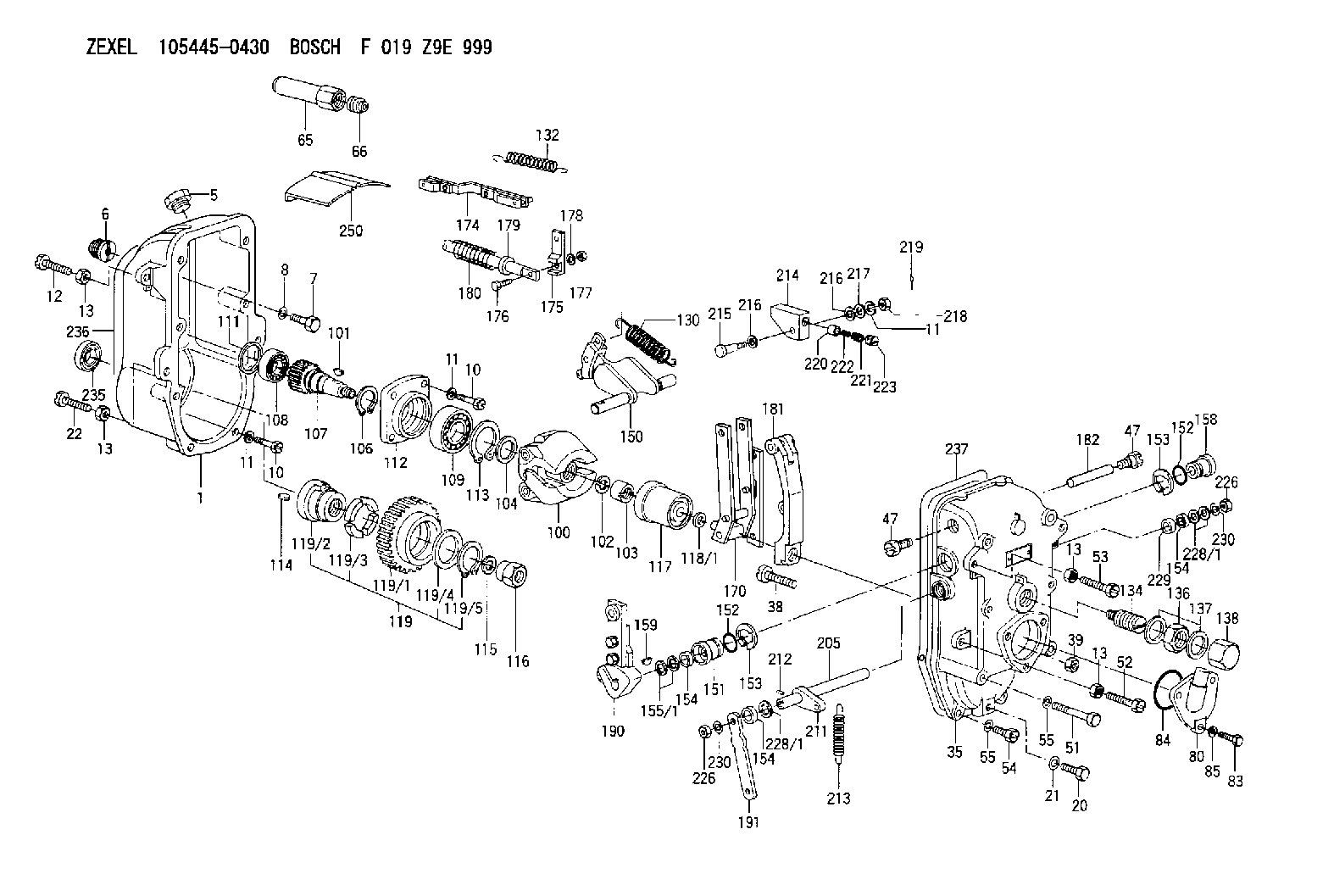
| 1. | [1] | 154003-1220 | GOVERNOR HOUSING |
| 5. | [1] | 154007-1400 | CAPSULE |
| 6. | [1] | 154007-0500 | ADAPTOR |
| 7. | [1] | 010038-1840 | BLEEDER SCREW M8P1.25L18 |
| 8. | [1] | 014110-8440 | LOCKING WASHER |
| 10. | [10] | 010038-2840 | BLEEDER SCREW |
| 10. | [10] | 010038-2840 | BLEEDER SCREW |
| 11. | [10] | 014110-8440 | LOCKING WASHER |
| 11. | [10] | 014110-8440 | LOCKING WASHER |
| 11. | [10] | 014110-8440 | LOCKING WASHER |
| 12. | [1] | 154010-6200 | BLEEDER SCREW |
| 13. | [4] | 029241-0020 | UNION NUT |
| 13. | [4] | 029241-0020 | UNION NUT |
| 13. | [4] | 029241-0020 | UNION NUT |
| 13. | [4] | 029241-0020 | UNION NUT |
| 20. | [1] | 029111-0030 | CAPSULE |
| 21. | [1] | 026510-1340 | GASKET D13.4&10.2T1 |
| 22. | [1] | 154034-0400 | BLEEDER SCREW |
| 35. | [1] | 154522-0020 | GOVERNOR COVER |
| 38. | [1] | 154031-0400 | FLAT-HEAD SCREW |
| 39. | [1] | 029201-0160 | UNION NUT |
| 47. | [2] | 154036-0400 | CAPSULE |
| 47. | [2] | 154036-0400 | CAPSULE |
| 51. | [6] | 010038-9140 | BLEEDER SCREW M8P1.25L95 |
| 52. | [1] | 154034-0400 | BLEEDER SCREW |
| 53. | [1] | 154034-0500 | BLEEDER SCREW |
| 54. | [2] | 010038-2840 | BLEEDER SCREW |
| 55. | [8] | 014110-8440 | LOCKING WASHER |
| 55. | [8] | 014110-8440 | LOCKING WASHER |
| 65. | [1] | 154050-5300 | CAP |
| 66. | [1] | 154007-0700 | BUSHING |
| 80. | [1] | 154060-8200 | COVER |
| 83. | [3] | 020508-1840 | BLEEDER SCREW M8P1.25L18 |
| 84. | [1] | 029635-5010 | O-RING |
| 85. | [3] | 014110-8440 | LOCKING WASHER |
| 100. | [1] | 154102-1720 | FLYWEIGHT ASSEMBLY |
| 101. | [1] | 025804-1610 | WOODRUFF KEY |
| 102. | [1] | 029321-4010 | LOCKING WASHER |
| 103. | [1] | 131325-2600 | UNION NUT |
| 104. | [1] | 154120-0200 | PLAIN WASHER |
| 106. | [1] | 016020-2510 | LOCKING WASHER |
| 107. | [1] | 154121-0600 | TOOTHED GEAR |
| 108. | [1] | 016630-2640 | BEARING PLATE |
| 109. | [1] | 028102-5010 | BEARING PLATE |
| 111. | [1] | 029313-2010 | SHIM D39.8&32T1 |
| 111A. | [1] | 029313-2020 | SHIM D39.8&32T0.2 |
| 112. | [1] | 154122-0200 | COVER |
| 113. | [1] | 016110-5210 | LOCKING WASHER |
| 114. | [1] | 025805-1910 | WOODRUFF KEY |
| 115. | [1] | 023641-8410 | LOCKING WASHER |
| 116. | [1] | 154011-0200 | UNION NUT |
| 117. | [1] | 154123-1820 | SLIDING PIECE |
| 118/1. | [0] | 029311-5020 | SHIM D20.5&15T0.05 |
| 118/1. | [0] | 029311-5030 | SHIM D20.5&15T0.1 |
| 118/1. | [0] | 029311-5050 | SHIM D20.5&15T0.2 |
| 118/1. | [0] | 029311-5060 | SHIM D20.5&15T0.4 |
| 118/1. | [0] | 029311-5080 | SHIM D20.5&15T0.5 |
| 118/1. | [0] | 029311-5120 | SHIM D20.5&15T0.3 |
| 119. | [1] | 154130-0620 | TOOTHED GEAR |
| 119/1. | [1] | 154130-0610 | TOOTHED GEAR |
| 119/2. | [1] | 154132-0220 | HOLDER |
| 119/3. | [4] | 153251-0200 | DAMPER |
| 119/4. | [1] | 153321-0100 | PLAIN WASHER |
| 119/5. | [1] | 016020-4010 | LOCKING WASHER |
| 130. | [1] | 154150-1700 | GOVERNOR SPRING |
| 132. | [1] | 154154-1800 | COILED SPRING |
| 134. | [1] | 154157-0520 | HEADLESS SCREW |
| 136. | [1] | 029203-0010 | UNION NUT |
| 137. | [2] | 026530-3640 | GASKET |
| 138. | [1] | 154159-0200 | CAP NUT |
| 150. | [1] | 154200-1621 | SWIVELLING LEVER |
| 151. | [1] | 154204-0301 | BUSHING |
| 152. | [2] | 029632-1010 | O-RING |
| 152. | [2] | 029632-1010 | O-RING |
| 153. | [2] | 016010-2010 | LOCKING WASHER |
| 153. | [2] | 016010-2010 | LOCKING WASHER |
| 154. | [3] | 029621-4000 | PACKING RING |
| 154. | [3] | 029621-4000 | PACKING RING |
| 154. | [3] | 029621-4000 | PACKING RING |
| 155/1. | [0] | 029311-4040 | SHIM D26&14.2T0.3 |
| 155/1. | [0] | 029311-4050 | SHIM D26&14.2T0.4 |
| 155/1. | [0] | 029311-4060 | SHIM D26&14.2T0.5 |
| 155/1. | [0] | 029311-4080 | SHIM D26&14.2T0.1 |
| 158. | [1] | 154204-3800 | BUSHING |
| 159. | [1] | 025803-1310 | WOODRUFF KEY |
| 170. | [1] | 154211-4820 | FORK LEVER |
| 174. | [1] | 154230-1620 | STRAP |
| 175. | [1] | 154232-0100 | CONNECTOR |
| 176. | [1] | 010006-1840 | BLEEDER SCREW M6P1L18 4T |
| 177. | [1] | 013020-6040 | UNION NUT M6P1H5 |
| 178. | [2] | 154233-0100 | TAB WASHER |
| 179. | [1] | 153400-0200 | SLOTTED WASHER |
| 180. | [1] | 153401-0300 | COILED SPRING |
| 181. | [1] | 154236-1700 | TENSIONING LEVER |
| 182. | [1] | 154237-0300 | BEARING PIN |
| 190. | [1] | 154303-4420 | CONTROL LEVER |
| 191. | [1] | 154300-1700 | CONTROL LEVER |
| 205. | [1] | 154330-1301 | LEVER SHAFT |
| 211. | [1] | 154331-0100 | CONTROL LEVER |
| 212. | [1] | 024330-2030 | BEARING PIN |
| 213. | [1] | 154332-0100 | COILED SPRING |
| 214. | [1] | 154333-0200 | CONTROL LEVER |
| 215. | [1] | 154334-0100 | BEARING PIN |
| 216. | [2] | 029301-0030 | PLAIN WASHER |
| 216. | [2] | 029301-0030 | PLAIN WASHER |
| 217. | [1] | 029300-8070 | PLAIN WASHER |
| 218. | [1] | 013020-8020 | UNION NUT M8P1.25H7 |
| 219. | [1] | 025520-1210 | SPLIT PIN |
| 220. | [1] | 154335-0100 | SLOTTED WASHER |
| 221. | [1] | 154336-0100 | COILED SPRING |
| 222. | [1] | 154336-0200 | COILED SPRING |
| 223. | [1] | 154337-0100 | CAPSULE |
| 226. | [2] | 013020-8040 | UNION NUT M8P1.25H7 |
| 226. | [2] | 013020-8040 | UNION NUT M8P1.25H7 |
| 228/1. | [0] | 029311-4040 | SHIM D26&14.2T0.3 |
| 228/1. | [0] | 029311-4050 | SHIM D26&14.2T0.4 |
| 228/1. | [0] | 029311-4050 | SHIM D26&14.2T0.4 |
| 228/1. | [0] | 029311-4060 | SHIM D26&14.2T0.5 |
| 228/1. | [0] | 029311-4080 | SHIM D26&14.2T0.1 |
| 229. | [1] | 154351-0600 | BUSHING |
| 230. | [2] | 014110-8440 | LOCKING WASHER |
| 230. | [2] | 014110-8440 | LOCKING WASHER |
| 235. | [1] | 155412-5500 | IMPELLER WHEEL |
| 236. | [1] | 154390-3000 | GASKET |
| 237. | [1] | 154390-3300 | GASKET |
| 250. | [1] | 154351-0520 | PLATE |
Cross reference number
Zexel num
Bosch num
Firm num
Name
Information:
Illustration 62 g02807941
Remove the plug
Remove plug (2) .
Illustration 63 g02807956
Set speed by turning adjusting screw
Adjust speed. If Ng exceeds TMI specifications, tighten the adjusting screw. If Ng is less than the specified value, loosen the adjusting screw.
Illustration 64 g02807957
Adjust the maximum-speed stopper bolt
Adjust the maximum-speed stopper bolt until the speed at the start of high-speed control is Nf.
Check that the no-load maximum speed is Ng (described in Step 1). Continue adjustment until the specified value is obtained.
Illustration 65 g02807958
Increase pump speed to make sure that the control rack position reaches Ra.
Illustration 66 g02807959
Full-load Adjustment
Illustration 67 g02807997
Install the cover and adjust full-load stopper bolt
Install cover (3) on governor using bolts and lockwashers (2). Use caution when installing the cover to make sure that the O-ring seal is in the seal groove.
Illustration 68 g02807999
Position the control lever at maximum-speed position.
Adjust full-load stopper bolt (1) to the f"ull-load fuel injection quantity" position. See TMI for the specifications (Point A).
Install cap.Control Lever Angle Measurement
Illustration 69 g02808016
Measuring control lever angle at the "full-speed" and "idling" positions.
Measuring the control lever angle at the "idling" and "full" positions.
If the angle is not as specified by TMI, replace the shifters shim. If the control lever is positioned toward the "full" position, replace the shifters shim with a thicker one. When control lever is toward the "idling" position, replace the shim with a thinner one.Check Starting Delivery
Illustration 70 g02808018
Remove measurement adapter
Remove measurement adapter (1) .
Illustration 71 g02808038
Cap must be installed to check delivery rate
Install cap (2) .
Run pump at speed specified in TMI.
Check delivery rate with specifications listed in TMI.
Stop pump rotation.
Illustration 72 g02808058
Adjusting screw for setting fuel flow
If delivery rate does not meet TMI specifications, remove cap (2), loosen lock nut, and adjust screw (3). Adjusting screw outward decreases fuel flow and inward increases fuel flow.
Install cap (2) and recheck delivery rate. Repeat Steps 2 through 6 until delivery rate is at specified value.Lockwiring Caps of Adjustment Screws
All adjustment stops (screws) that directly affect engine performance should be lockwired after adjustment. Do not readjust any stop without using the test stand can adversely affect the engine and engine performance.