Information governor
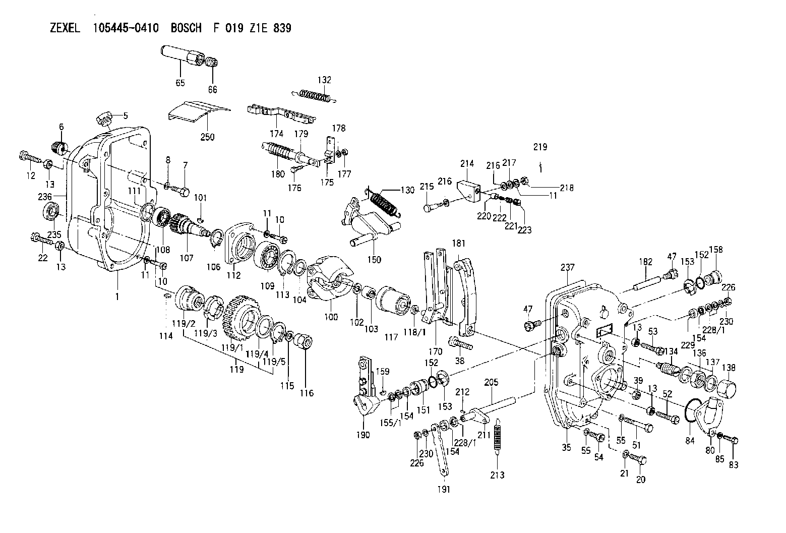
BOSCH
F 019 Z1E 839
f019z1e839
ZEXEL
105445-0410
1054450410
Rating:
Scheme ###:
| 1. | [1] | 154003-1220 | GOVERNOR HOUSING |
| 5. | [1] | 154007-1400 | CAPSULE |
| 6. | [1] | 154007-0500 | ADAPTOR |
| 7. | [1] | 010038-1840 | BLEEDER SCREW M8P1.25L18 |
| 8. | [1] | 014110-8440 | LOCKING WASHER |
| 10. | [10] | 010038-2840 | BLEEDER SCREW |
| 10. | [10] | 010038-2840 | BLEEDER SCREW |
| 11. | [10] | 014110-8440 | LOCKING WASHER |
| 11. | [10] | 014110-8440 | LOCKING WASHER |
| 11. | [10] | 014110-8440 | LOCKING WASHER |
| 12. | [1] | 154010-6200 | BLEEDER SCREW |
| 13. | [4] | 029241-0020 | UNION NUT |
| 13. | [4] | 029241-0020 | UNION NUT |
| 13. | [4] | 029241-0020 | UNION NUT |
| 13. | [4] | 029241-0020 | UNION NUT |
| 20. | [1] | 029111-0030 | CAPSULE |
| 21. | [1] | 026510-1340 | GASKET D13.4&10.2T1 |
| 22. | [1] | 154034-0400 | BLEEDER SCREW |
| 35. | [1] | 154522-0020 | GOVERNOR COVER |
| 38. | [1] | 154031-0400 | FLAT-HEAD SCREW |
| 39. | [1] | 029201-0160 | UNION NUT |
| 47. | [2] | 154036-0400 | CAPSULE |
| 47. | [2] | 154036-0400 | CAPSULE |
| 51. | [6] | 010038-9140 | BLEEDER SCREW M8P1.25L95 |
| 52. | [1] | 154034-0400 | BLEEDER SCREW |
| 53. | [1] | 154034-0500 | BLEEDER SCREW |
| 54. | [2] | 010038-2840 | BLEEDER SCREW |
| 55. | [8] | 014110-8440 | LOCKING WASHER |
| 55. | [8] | 014110-8440 | LOCKING WASHER |
| 65. | [1] | 154050-5300 | CAP |
| 66. | [1] | 154007-0700 | BUSHING |
| 80. | [1] | 154060-8200 | COVER |
| 83. | [3] | 020508-1840 | BLEEDER SCREW M8P1.25L18 |
| 84. | [1] | 029635-5010 | O-RING |
| 85. | [3] | 014110-8440 | LOCKING WASHER |
| 100. | [1] | 154102-1720 | FLYWEIGHT ASSEMBLY |
| 101. | [1] | 025804-1610 | WOODRUFF KEY |
| 102. | [1] | 029321-4010 | LOCKING WASHER |
| 103. | [1] | 131325-2600 | UNION NUT |
| 104. | [1] | 154120-0200 | PLAIN WASHER |
| 106. | [1] | 016020-2510 | LOCKING WASHER |
| 107. | [1] | 154121-0900 | TOOTHED GEAR |
| 108. | [1] | 016630-2640 | BEARING PLATE |
| 109. | [1] | 028102-5010 | BEARING PLATE |
| 111. | [1] | 029313-2010 | SHIM D39.8&32T1 |
| 111A. | [1] | 029313-2020 | SHIM D39.8&32T0.2 |
| 112. | [1] | 154122-0200 | COVER |
| 113. | [1] | 016110-5210 | LOCKING WASHER |
| 114. | [1] | 025805-1910 | WOODRUFF KEY |
| 115. | [1] | 023641-8410 | LOCKING WASHER |
| 116. | [1] | 154011-0200 | UNION NUT |
| 117. | [1] | 154123-1820 | SLIDING PIECE |
| 118/1. | [0] | 029311-5020 | SHIM D20.5&15T0.05 |
| 118/1. | [0] | 029311-5030 | SHIM D20.5&15T0.1 |
| 118/1. | [0] | 029311-5050 | SHIM D20.5&15T0.2 |
| 118/1. | [0] | 029311-5060 | SHIM D20.5&15T0.4 |
| 118/1. | [0] | 029311-5080 | SHIM D20.5&15T0.5 |
| 118/1. | [0] | 029311-5120 | SHIM D20.5&15T0.3 |
| 119. | [1] | 154130-0920 | TOOTHED GEAR |
| 119/1. | [1] | 154130-0910 | TOOTHED GEAR |
| 119/2. | [1] | 154132-0220 | HOLDER |
| 119/3. | [4] | 153251-0200 | DAMPER |
| 119/4. | [1] | 153321-0100 | PLAIN WASHER |
| 119/5. | [1] | 016020-4010 | LOCKING WASHER |
| 130. | [1] | 154150-1700 | GOVERNOR SPRING |
| 132. | [1] | 154154-1800 | COILED SPRING |
| 134. | [1] | 154157-3620 | HEADLESS SCREW |
| 136. | [1] | 029203-0010 | UNION NUT |
| 137. | [2] | 026530-3640 | GASKET |
| 138. | [1] | 154159-1500 | CAP NUT |
| 150. | [1] | 154200-1621 | SWIVELLING LEVER |
| 151. | [1] | 154204-0301 | BUSHING |
| 152. | [2] | 029632-1010 | O-RING |
| 152. | [2] | 029632-1010 | O-RING |
| 153. | [2] | 016010-2010 | LOCKING WASHER |
| 153. | [2] | 016010-2010 | LOCKING WASHER |
| 154. | [3] | 029621-4000 | PACKING RING |
| 154. | [3] | 029621-4000 | PACKING RING |
| 154. | [3] | 029621-4000 | PACKING RING |
| 155/1. | [0] | 029311-4040 | SHIM D26&14.2T0.3 |
| 155/1. | [0] | 029311-4050 | SHIM D26&14.2T0.4 |
| 155/1. | [0] | 029311-4060 | SHIM D26&14.2T0.5 |
| 155/1. | [0] | 029311-4080 | SHIM D26&14.2T0.1 |
| 158. | [1] | 154204-3800 | BUSHING |
| 159. | [1] | 025803-1310 | WOODRUFF KEY |
| 170. | [1] | 154211-4820 | FORK LEVER |
| 174. | [1] | 154230-1620 | STRAP |
| 175. | [1] | 154232-0100 | CONNECTOR |
| 176. | [1] | 010006-1840 | BLEEDER SCREW M6P1L18 4T |
| 177. | [1] | 013020-6040 | UNION NUT M6P1H5 |
| 178. | [2] | 154233-0100 | TAB WASHER |
| 179. | [1] | 153400-0200 | SLOTTED WASHER |
| 180. | [1] | 153401-0300 | COILED SPRING |
| 181. | [1] | 154236-1700 | TENSIONING LEVER |
| 182. | [1] | 154237-0300 | BEARING PIN |
| 190. | [1] | 154303-4420 | CONTROL LEVER |
| 191. | [1] | 154300-1700 | CONTROL LEVER |
| 205. | [1] | 154330-1301 | LEVER SHAFT |
| 211. | [1] | 154331-0100 | CONTROL LEVER |
| 212. | [1] | 024330-2030 | BEARING PIN |
| 213. | [1] | 154332-0100 | COILED SPRING |
| 214. | [1] | 154333-0200 | CONTROL LEVER |
| 215. | [1] | 154334-0100 | BEARING PIN |
| 216. | [2] | 029301-0030 | PLAIN WASHER |
| 216. | [2] | 029301-0030 | PLAIN WASHER |
| 217. | [1] | 029300-8070 | PLAIN WASHER |
| 218. | [1] | 013020-8020 | UNION NUT M8P1.25H7 |
| 219. | [1] | 025520-1210 | SPLIT PIN |
| 220. | [1] | 154335-0100 | SLOTTED WASHER |
| 221. | [1] | 154336-0100 | COILED SPRING |
| 222. | [1] | 154336-0200 | COILED SPRING |
| 223. | [1] | 154337-0100 | CAPSULE |
| 226. | [2] | 013020-8040 | UNION NUT M8P1.25H7 |
| 226. | [2] | 013020-8040 | UNION NUT M8P1.25H7 |
| 228/1. | [0] | 029311-4040 | SHIM D26&14.2T0.3 |
| 228/1. | [0] | 029311-4050 | SHIM D26&14.2T0.4 |
| 228/1. | [0] | 029311-4060 | SHIM D26&14.2T0.5 |
| 228/1. | [0] | 029311-4080 | SHIM D26&14.2T0.1 |
| 228/1. | [0] | 029311-4080 | SHIM D26&14.2T0.1 |
| 229. | [1] | 154351-0600 | BUSHING |
| 230. | [2] | 014110-8440 | LOCKING WASHER |
| 230. | [2] | 014110-8440 | LOCKING WASHER |
| 235. | [1] | 155412-5500 | IMPELLER WHEEL |
| 236. | [1] | 154390-3000 | GASKET |
| 237. | [1] | 154390-3300 | GASKET |
| 250. | [1] | 154351-0520 | PLATE |
Include in #1:
103672-0081
as GOVERNOR
Cross reference number
Zexel num
Bosch num
Firm num
Name
Information:
Start By:a. remove cylinder head assemblyb. remove front housing groupc. remove flywheel housingd. remove crankshaft rear seal assemblye. remove piston and connecting rod assemblies 1. Remove bolts (1). Remove main bearing caps (2). Remove thrust bearings (3) from the center main. Main bearing caps are identified by numbers one through seven. Unmarked caps should be marked by stamping the appropriate number toward the right side on the bottom prior to the removal. 2. Install a suitable size bolt in each end of the crankshaft as shown. Fasten two lifting straps (4) to the bolts in the crankshaft and to a hoist as shown. Carefully, remove the crankshaft. The appropriate weight of the crankshaft is 129 kg (285 lb).3. Remove the upper portions of the main bearings. The following steps are for the installation of the crankshaft.
Be sure the main bearing tabs engage with the grooves in the block and cap.
4. Position the upper portion of the main bearings in the cylinder block. Lower the main bearing portion in caps (2). Be sure everything is clean and only the bearing face is lubricated with clean engine oil.5. Fasten a hoist to the crankshaft, and position it in the cylinder block. 6. Install thrust bearings (3).7. Install main bearing caps (2) with the part numbers toward the right hand side of the cylinder block. Take care to ensure the caps are numbered one through seven from the front of the engine. Put clean engine oil or molylube on the bolt threads and the washer face; then install bolts (1). Tighten the bolts on the side where the main bearing tabs are located to a torque of 95 5 N m (70 4 lb ft). Tighten the bolts on the opposite side to a torque of 95 5 N m (70 4 lb ft).8. Put a mark on each bolt head and the bearing caps. Turn the bolts that are opposite the main bearing tabs an additional 90° 5° turn. Then turn the bolts on the side where the main bearing tabs are located an additional 90° 5° turn.
Typical Example9. Use tooling (A) to measure crankshaft end play. The crankshaft end play must be 0.10 to 0.50 mm (.004 to .020 in).End By:a. install piston and connecting rod assembliesb. install crankshaft rear seal assemblyc. install flywheel housingd. install front housing groupe. install cylinder head assembly