Information governor
BOSCH
9 420 610 280
9420610280
ZEXEL
105445-0370
1054450370
Rating:
Scheme ###:
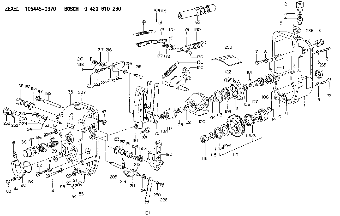
| 1. | [1] | 154003-0820 | GOVERNOR HOUSING |
| 2. | [1] | 155406-0620 | AIR FILTER |
| 3. | [1] | 026512-1540 | GASKET D15.4&12.2T1.50 |
| 4. | [1] | 154007-0100 | ADAPTOR |
| 5. | [1] | 154007-1400 | CAPSULE |
| 6. | [1] | 154007-0500 | ADAPTOR |
| 7. | [1] | 010038-1840 | BLEEDER SCREW M8P1.25L18 |
| 8. | [1] | 154008-0100 | TAB WASHER |
| 10. | [4] | 010508-2540 | FLAT-HEAD SCREW M8P1.25L25 |
| 11. | [9] | 014110-8410 | LOCKING WASHER |
| 11. | [9] | 014110-8410 | LOCKING WASHER |
| 12. | [1] | 154010-1800 | FLAT-HEAD SCREW |
| 13. | [4] | 029241-0020 | UNION NUT |
| 13. | [4] | 029241-0020 | UNION NUT |
| 13. | [4] | 029241-0020 | UNION NUT |
| 13. | [4] | 029241-0020 | UNION NUT |
| 20. | [1] | 029111-0030 | CAPSULE |
| 21. | [1] | 026510-1340 | GASKET D13.4&10.2T1 |
| 22. | [1] | 154034-0400 | BLEEDER SCREW |
| 35. | [1] | 154522-0220 | GOVERNOR COVER |
| 38. | [1] | 154031-0400 | FLAT-HEAD SCREW |
| 39. | [1] | 029201-0160 | UNION NUT |
| 47. | [2] | 154036-0400 | CAPSULE |
| 47. | [2] | 154036-0400 | CAPSULE |
| 51. | [6] | 010038-9140 | BLEEDER SCREW M8P1.25L95 |
| 52. | [1] | 154034-0400 | BLEEDER SCREW |
| 53. | [1] | 154034-0500 | BLEEDER SCREW |
| 54. | [2] | 010038-2840 | BLEEDER SCREW |
| 55. | [8] | 014110-8410 | LOCKING WASHER |
| 55. | [8] | 014110-8410 | LOCKING WASHER |
| 65. | [1] | 153022-3320 | STOPPING DEVICE |
| 80. | [1] | 154060-0620 | COVER |
| 81. | [1] | 133030-1320 | LEVEL INDICATOR |
| 83. | [3] | 020508-1840 | BLEEDER SCREW M8P1.25L18 |
| 84. | [1] | 029635-5010 | O-RING |
| 85. | [3] | 014110-8410 | LOCKING WASHER |
| 100. | [1] | 154102-1720 | FLYWEIGHT ASSEMBLY |
| 101. | [1] | 025804-1610 | WOODRUFF KEY |
| 102. | [1] | 029321-4010 | LOCKING WASHER |
| 103. | [1] | 131325-2600 | UNION NUT |
| 104. | [1] | 154120-0200 | PLAIN WASHER |
| 106. | [1] | 016020-2510 | LOCKING WASHER |
| 107. | [1] | 154121-0600 | TOOTHED GEAR |
| 108. | [1] | 016630-2640 | BEARING PLATE |
| 109. | [1] | 028102-5010 | BEARING PLATE |
| 111. | [1] | 029313-2010 | SHIM D39.8&32T1 |
| 111A. | [1] | 029313-2020 | SHIM D39.8&32T0.2 |
| 112. | [1] | 154122-0200 | COVER |
| 113. | [1] | 016110-5210 | LOCKING WASHER |
| 114. | [1] | 025805-1910 | WOODRUFF KEY |
| 115. | [1] | 023641-8410 | LOCKING WASHER |
| 116. | [1] | 154011-0200 | UNION NUT |
| 117. | [1] | 154123-2020 | SLIDING PIECE |
| 118/1. | [0] | 029311-5020 | SHIM D20.5&15T0.05 |
| 118/1. | [0] | 029311-5030 | SHIM D20.5&15T0.1 |
| 118/1. | [0] | 029311-5050 | SHIM D20.5&15T0.2 |
| 118/1. | [0] | 029311-5060 | SHIM D20.5&15T0.4 |
| 118/1. | [0] | 029311-5080 | SHIM D20.5&15T0.5 |
| 118/1. | [0] | 029311-5120 | SHIM D20.5&15T0.3 |
| 119. | [1] | 154130-0620 | TOOTHED GEAR |
| 119/3. | [4] | 153251-0200 | DAMPER |
| 119/4. | [1] | 153321-0100 | PLAIN WASHER |
| 119/5. | [1] | 016020-4010 | LOCKING WASHER |
| 122. | [4] | 020308-2540 | BLEEDER SCREW M8P1.25L25 |
| 130. | [1] | 154150-6600 | GOVERNOR SPRING |
| 132. | [1] | 154154-2500 | COILED SPRING |
| 134. | [1] | 154157-0520 | HEADLESS SCREW |
| 136. | [1] | 029203-0010 | UNION NUT |
| 137. | [2] | 026530-3640 | GASKET |
| 138. | [1] | 154159-0200 | CAP NUT |
| 150. | [1] | 154200-4221 | SWIVELLING LEVER |
| 151. | [1] | 154204-0301 | BUSHING |
| 152. | [2] | 029632-1010 | O-RING |
| 152. | [2] | 029632-1010 | O-RING |
| 153. | [2] | 016010-2010 | LOCKING WASHER |
| 153. | [2] | 016010-2010 | LOCKING WASHER |
| 154. | [3] | 029621-4000 | PACKING RING |
| 154. | [3] | 029621-4000 | PACKING RING |
| 154. | [3] | 029621-4000 | PACKING RING |
| 155/1. | [0] | 029311-4040 | SHIM D26&14.2T0.3 |
| 155/1. | [0] | 029311-4050 | SHIM D26&14.2T0.4 |
| 155/1. | [0] | 029311-4060 | SHIM D26&14.2T0.5 |
| 155/1. | [0] | 029311-4080 | SHIM D26&14.2T0.1 |
| 158. | [1] | 154204-3800 | BUSHING |
| 159. | [1] | 025803-1310 | WOODRUFF KEY |
| 170. | [1] | 154211-5120 | FORK LEVER |
| 174. | [1] | 154230-4620 | STRAP |
| 175. | [1] | 154232-0100 | CONNECTOR |
| 176. | [1] | 010006-1840 | BLEEDER SCREW M6P1L18 4T |
| 177. | [1] | 013020-6040 | UNION NUT M6P1H5 |
| 178. | [2] | 154233-0100 | TAB WASHER |
| 179. | [1] | 153400-0200 | SLOTTED WASHER |
| 180. | [1] | 153401-0300 | COILED SPRING |
| 181. | [1] | 154236-1700 | TENSIONING LEVER |
| 182. | [1] | 154237-0300 | BEARING PIN |
| 184. | [1] | 025520-1510 | SPLIT PIN |
| 185. | [1] | 029300-6150 | SHIM D12&6.2T0.3 |
| 190. | [1] | 154303-5520 | CONTROL LEVER |
| 191. | [1] | 154300-1700 | CONTROL LEVER |
| 205. | [1] | 154330-1301 | LEVER SHAFT |
| 211. | [1] | 154331-0100 | CONTROL LEVER |
| 212. | [1] | 024330-2030 | BEARING PIN |
| 213. | [1] | 154332-0100 | COILED SPRING |
| 214. | [1] | 154333-0200 | CONTROL LEVER |
| 215. | [1] | 154334-0100 | BEARING PIN |
| 216. | [2] | 029301-0030 | PLAIN WASHER |
| 216. | [2] | 029301-0030 | PLAIN WASHER |
| 217. | [1] | 029300-8070 | PLAIN WASHER |
| 218. | [1] | 013020-8020 | UNION NUT M8P1.25H7 |
| 219. | [4] | 025520-1210 | SPLIT PIN |
| 220. | [1] | 154335-0100 | SLOTTED WASHER |
| 221. | [1] | 154336-0100 | COILED SPRING |
| 222. | [1] | 154336-0200 | COILED SPRING |
| 223. | [1] | 154337-0100 | CAPSULE |
| 226. | [2] | 013020-8040 | UNION NUT M8P1.25H7 |
| 226. | [2] | 013020-8040 | UNION NUT M8P1.25H7 |
| 229. | [1] | 154351-0600 | BUSHING |
| 230. | [2] | 014110-8410 | LOCKING WASHER |
| 230. | [2] | 014110-8410 | LOCKING WASHER |
| 235. | [1] | 029622-5010 | PACKING RING |
| 236. | [1] | 154350-1000 | GASKET |
| 237. | [1] | 154390-3300 | GASKET |
| 250. | [1] | 154351-0520 | PLATE |
| 252. | [1] | 029332-6030 | GASKET |
| 253. | [1] | 131034-1400 | CAPSULE |
Cross reference number
Zexel num
Bosch num
Firm num
Name
105445-0370
GOVERNOR
K 14JC MECHANICAL GOVERNOR GOV RSUV(D) GOV
K 14JC MECHANICAL GOVERNOR GOV RSUV(D) GOV
Information:
Start By:a. remove cylinder head assemblyb. remove oil pan 1. Remove the bolt that holds piston cooling jet (1) in position. Remove the piston cooling jet.2. Check the connecting rods and caps for their identification mark and location. The connecting rod and the rod cap should have the cylinder number etched on the right side as indicated by the arrow. If not marked, etch each unmarked connecting rod/or cap during removal.3. Remove rod cap bolts (2) and the cap from the connecting rod. Remove the lower half of the bearing from the cap. 4. Push piston and connecting rod (4) away from the crankshaft; then remove the upper half of rod bearing (5).5. Remove the piston and connecting rod from the cylinder block.6. Repeat Steps 1 through 5 for the other piston and connecting rod assemblies. The following steps are for the installation of the pistons and connecting rod assemblies.7. Put clean engine oil on the piston rings, piston in the cylinder bore. 8. Position the piston ring end gaps 120° apart. Install tool (A) to compress the rings.9. With the number one crankshaft throw at bottom center, install the piston and connecting rod. Some engines use pistons which have the word "FRONT" stamped on the crown of the piston. Be sure the word "FRONT" is toward the front of the engine when the piston is installed. The etched number on the connecting rod must be on the right side and must be installed in the corresponding cylinder.10. Line up the connecting rod with the crankshaft. Using a soft faced hammer, carefully tap the piston into the cylinder bore until tooling (A) comes off of the piston.11. Before the connecting rod comes in contact with crankshaft, install the upper half of the rod bearing. Be sure the bearing tab properly engages with the slot in the connecting rod.12. Put clean engine oil on the upper rod bearing surface. Using a soft faced hammer, tap the piston down while guiding the connecting rod onto the crankshaft.13. Position the lower half of the rod bearing in the corresponding numbered rod cap. Be sure the bearing tab engages with the grove in the rod caps.14. Put clean engine oil on the lower rod bearing surface; then install the rod cap. Install the bearing cap on the connecting rod with the number on the bearing (rod) cap on the same side and same number as on the connecting rod.15. Put 2P2506 Thread Lubricant on the threads of rod cap bolts (1) and the seating surfaces of the caps. Install rod cap bolts (1). Tighten them to a torque of 130 7 N m (95 5 lb ft). Mark each bolt head, and then tighten each rod cap bolt an additional 1/6 60 5 ( turn).16. Repeat Steps 7 through 15 for the remainder of the piston and connecting rods.17. Reinstall piston cooling jets (1).End By:a. install oil panb. install cylinder head assemblyDisassemble & Assemble Piston & Connecting Rod Assemblies
Start
Start