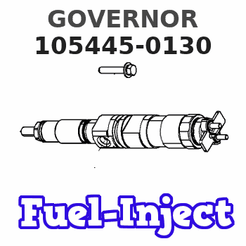
Information governor
BOSCH
F 019 Z1F 264
f019z1f264
ZEXEL
105445-0130
1054450130
Rating:
Scheme ###:
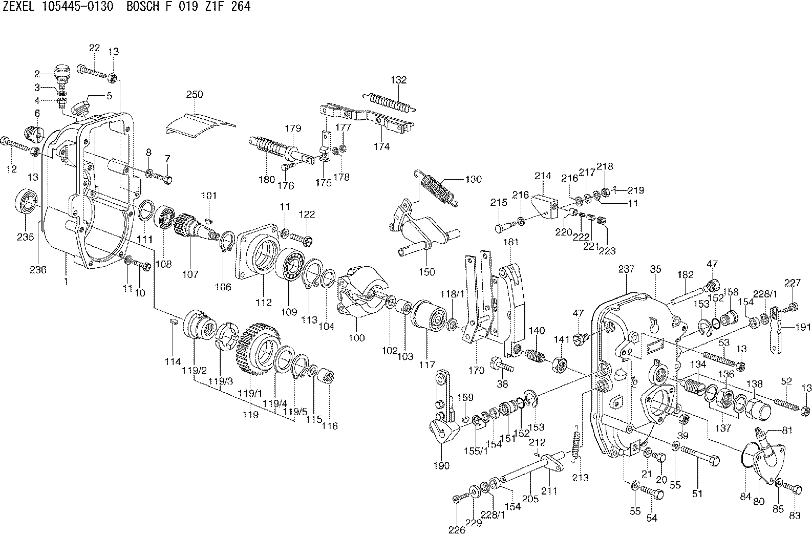
| 1. | [1] | 154003-0820 | GOVERNOR HOUSING |
| 2. | [1] | 155406-0620 | AIR FILTER |
| 3. | [1] | 026512-1540 | GASKET |
| 4. | [1] | 154007-0100 | ADAPTOR |
| 5. | [1] | 154007-1400 | CAPSULE |
| 6. | [1] | 154007-0500 | ADAPTOR |
| 7. | [1] | 010038-1840 | BLEEDER SCREW |
| 8. | [1] | 154008-0100 | TAB WASHER |
| 10. | [4] | 010508-2540 | FLAT-HEAD SCREW |
| 11. | [9] | 014110-8440 | LOCKING WASHER D15.4&8.2T2 |
| 11. | [9] | 014110-8440 | LOCKING WASHER D15.4&8.2T2 |
| 11. | [9] | 014110-8440 | LOCKING WASHER D15.4&8.2T2 |
| 12. | [1] | 154034-2100 | BLEEDER SCREW |
| 13. | [4] | 029241-0020 | UNION NUT |
| 13. | [4] | 029241-0020 | UNION NUT |
| 13. | [4] | 029241-0020 | UNION NUT |
| 13. | [4] | 029241-0020 | UNION NUT |
| 20. | [1] | 029111-0030 | CAPSULE |
| 21. | [1] | 026510-1340 | GASKET |
| 22. | [1] | 154034-0400 | BLEEDER SCREW |
| 35. | [1] | 154522-0020 | GOVERNOR COVER |
| 38. | [1] | 154031-0400 | FLAT-HEAD SCREW |
| 39. | [1] | 029201-0160 | UNION NUT |
| 47. | [2] | 154036-0400 | CAPSULE |
| 47. | [2] | 154036-0400 | CAPSULE |
| 51. | [6] | 010038-9140 | BLEEDER SCREW |
| 52. | [1] | 154034-0400 | BLEEDER SCREW |
| 53. | [1] | 154010-1800 | FLAT-HEAD SCREW |
| 54. | [2] | 010038-2840 | BLEEDER SCREW |
| 55. | [8] | 014110-8440 | LOCKING WASHER D15.4&8.2T2 |
| 55. | [8] | 014110-8440 | LOCKING WASHER D15.4&8.2T2 |
| 80. | [1] | 154060-0620 | COVER |
| 81. | [1] | 133030-0520 | LEVEL INDICATOR |
| 83. | [3] | 020508-1840 | BLEEDER SCREW |
| 84. | [1] | 029635-5010 | O-RING |
| 85. | [3] | 014110-8440 | LOCKING WASHER D15.4&8.2T2 |
| 100. | [1] | 154102-1720 | FLYWEIGHT ASSEMBLY |
| 101. | [1] | 025804-1610 | WOODRUFF KEY |
| 102. | [1] | 029321-4010 | LOCKING WASHER |
| 103. | [1] | 131325-2600 | UNION NUT |
| 104. | [1] | 154120-0200 | PLAIN WASHER |
| 106. | [1] | 016020-2510 | LOCKING WASHER |
| 107. | [1] | 154121-0700 | TOOTHED GEAR |
| 108. | [1] | 016630-2640 | BEARING PLATE |
| 109. | [1] | 028102-5010 | BEARING PLATE |
| 111. | [1] | 029313-2010 | SHIM |
| 111A. | [1] | 029313-2020 | SHIM |
| 112. | [1] | 154122-0200 | COVER |
| 113. | [1] | 016110-5210 | LOCKING WASHER |
| 114. | [1] | 025805-1910 | WOODRUFF KEY |
| 115. | [1] | 023641-8410 | LOCKING WASHER |
| 116. | [1] | 154011-0200 | UNION NUT |
| 117. | [1] | 154123-1820 | SLIDING PIECE |
| 118/1. | [0] | 029311-5020 | SHIM D20.5&15T0.05 |
| 118/1. | [0] | 029311-5030 | SHIM D20.5&15T0.1 |
| 118/1. | [0] | 029311-5050 | SHIM D20.5&15T0.2 |
| 118/1. | [0] | 029311-5060 | SHIM D20.5&15T0.4 |
| 118/1. | [0] | 029311-5080 | SHIM D26.8&15T0.5 |
| 118/1. | [0] | 029311-5120 | SHIM D20.5&15T0.3 |
| 119. | [1] | 154130-0720 | TOOTHED GEAR |
| 119/1. | [1] | 154130-0710 | TOOTHED GEAR |
| 119/2. | [1] | 154132-0220 | HOLDER |
| 119/3. | [4] | 153251-0200 | DAMPER |
| 119/4. | [1] | 153321-0100 | PLAIN WASHER |
| 119/5. | [1] | 016020-4010 | LOCKING WASHER |
| 122. | [4] | 020308-2540 | BLEEDER SCREW |
| 130. | [1] | 154150-6600 | GOVERNOR SPRING |
| 132. | [1] | 154154-1800 | COILED SPRING |
| 134. | [1] | 154157-1420 | HEADLESS SCREW |
| 136. | [1] | 029203-0060 | UNION NUT |
| 137. | [2] | 026530-3640 | GASKET |
| 138. | [1] | 154159-0200 | CAP NUT |
| 140. | [1] | 154175-1921 | HEADLESS SCREW |
| 141. | [1] | 139220-0400 | UNION NUT |
| 150. | [1] | 154200-1621 | SWIVELLING LEVER |
| 151. | [1] | 154204-0301 | BUSHING |
| 152. | [2] | 029632-1010 | O-RING |
| 152. | [2] | 029632-1010 | O-RING |
| 153. | [2] | 016010-2010 | LOCKING WASHER |
| 153. | [2] | 016010-2010 | LOCKING WASHER |
| 154. | [3] | 029621-4000 | PACKING RING |
| 154. | [3] | 029621-4000 | PACKING RING |
| 154. | [3] | 029621-4000 | PACKING RING |
| 155/1. | [0] | 029311-4040 | SHIM D26&14.2T0.3 |
| 155/1. | [0] | 029311-4050 | SHIM D26&14.2T0.4 |
| 155/1. | [0] | 029311-4060 | SHIM D26&14.2T0.5 |
| 155/1. | [0] | 029311-4080 | SHIM D26&14.2T0.1 |
| 158. | [1] | 154204-3800 | BUSHING |
| 159. | [1] | 025803-1310 | WOODRUFF KEY 13 MM |
| 170. | [1] | 154211-4820 | FORK LEVER |
| 174. | [1] | 154230-1520 | STRAP |
| 175. | [1] | 154232-0100 | CONNECTOR |
| 176. | [1] | 010006-1840 | BLEEDER SCREW |
| 177. | [1] | 013020-6040 | UNION NUT |
| 178. | [2] | 154233-0100 | TAB WASHER |
| 179. | [1] | 153400-0200 | SLOTTED WASHER |
| 180. | [1] | 153401-0300 | COILED SPRING |
| 181. | [1] | 154236-0800 | TENSIONING LEVER |
| 182. | [1] | 154237-0300 | BEARING PIN |
| 190. | [1] | 154303-4420 | CONTROL LEVER |
| 191. | [1] | 154300-0300 | CONTROL LEVER |
| 205. | [1] | 154330-1500 | LEVER SHAFT |
| 211. | [1] | 154331-0100 | CONTROL LEVER |
| 212. | [1] | 024330-2030 | BEARING PIN |
| 213. | [1] | 154332-0100 | COILED SPRING |
| 214. | [1] | 154333-0200 | CONTROL LEVER |
| 215. | [1] | 154334-0100 | BEARING PIN |
| 216. | [2] | 029301-0030 | PLAIN WASHER |
| 216. | [2] | 029301-0030 | PLAIN WASHER |
| 217. | [1] | 029300-8070 | PLAIN WASHER |
| 218. | [1] | 013020-8020 | UNION NUT |
| 219. | [1] | 025520-1210 | SPLIT PIN |
| 220. | [1] | 154335-0100 | SLOTTED WASHER |
| 221. | [1] | 154336-0100 | COILED SPRING |
| 222. | [1] | 154336-0200 | COILED SPRING |
| 223. | [1] | 154337-0100 | CAPSULE |
| 226. | [1] | 021306-1540 | FLAT-HEAD SCREW |
| 227. | [1] | 020006-1640 | BLEEDER SCREW |
| 228/1. | [0] | 029311-4040 | SHIM D26&14.2T0.3 |
| 228/1. | [0] | 029311-4040 | SHIM D26&14.2T0.3 |
| 228/1. | [0] | 029311-4050 | SHIM D26&14.2T0.4 |
| 228/1. | [0] | 029311-4060 | SHIM D26&14.2T0.5 |
| 228/1. | [0] | 029311-4080 | SHIM D26&14.2T0.1 |
| 229. | [1] | 154350-0700 | PLATE |
| 235. | [1] | 029622-5010 | PACKING RING |
| 236. | [1] | 154350-1000 | GASKET |
| 237. | [1] | 154390-3300 | GASKET |
| 250. | [1] | 154351-0520 | PLATE |
Include in #1:
103662-0730
as GOVERNOR
Cross reference number
Zexel num
Bosch num
Firm num
Name
105445-0130
GOVERNOR
K 14JC MECHANICAL GOVERNOR GOV RSUV(D) GOV
K 14JC MECHANICAL GOVERNOR GOV RSUV(D) GOV
Information:
It is not necessary to remove the cylinder head assembly for removal of the camshaft.3. Wire the cam roller followers up off of the camshaft as shown. Do this at each cylinder.
Typical Example3. Remove thrust pin (1), and remove camshaft assembly (2) from the engine. The following steps are for the installation of the camshaft assembly.4. Be sure the camshaft assembly is thoroughly clean. Put clean engine oil on the lobes and journals of the camshaft assembly. When installing the camshaft, rotating it in both clockwise and counterclockwise directions will help prevent it from binding in the bearing bores.5. Carefully install camshaft assembly (2) in the engine.
Camshaft Timing
When installing the camshaft assembly, be sure the number one cylinder is at (TDC) top dead center of the compression stroke with the timing pin installed in the flywheel. Camshaft timing is very important. The timing mark on the camshaft drive gear must line up with the idler gear timing mark as shown in the illustration. For more information about timing of engine, refer to the "Specifications" module, Form No. SENR5560.
6. With the camshaft properly timed and positioned, install thrust pin (1). Tighten thrust pin (1) to a torque of 48 7 N m (35 5 lb ft). Remove the wires that were used to hold the cam roller followers up off of the camshaft.End By:a. install front housing groupb. install speed/timing sensorc. install vibration damper and pulleyd. install alternatore. install drive belt and belt tightener groupf. install fuel transfer pumpg. install electronic unit injectorsh. install rocker arm assemblies and push rodsDisassemble & Assemble Camshaft Assembly
Start By:a. remove camshaft assembly1. Wrap camshaft portion of camshaft assembly with paper towels to protect the camshaft from being damaged.
Care must be taken not to allow the camshaft to fall to the floor when pressing it from the drive gear. Also, be sure that a camshaft lobe does not catch on the press plates.
2. Place the camshaft assembly in a press. Press camshaft (3) from drive gear (1).3. Remove woodruff key (2) from the camshaft. The following steps are for the assembly of the camshaft and the gear assembly.4. Install woodruff key (2) in the camshaft.5. Heat drive gear (1) to a maximum temperature of 300 C (572 F) for 30 minutes. Install the drive gear on the end of camshaft (3). Be sure woodruff key (2) is properly aligned and the drive gear makes contact with the shoulder on the end of the camshaft.End By:a. install camshaft assembly