Information governor
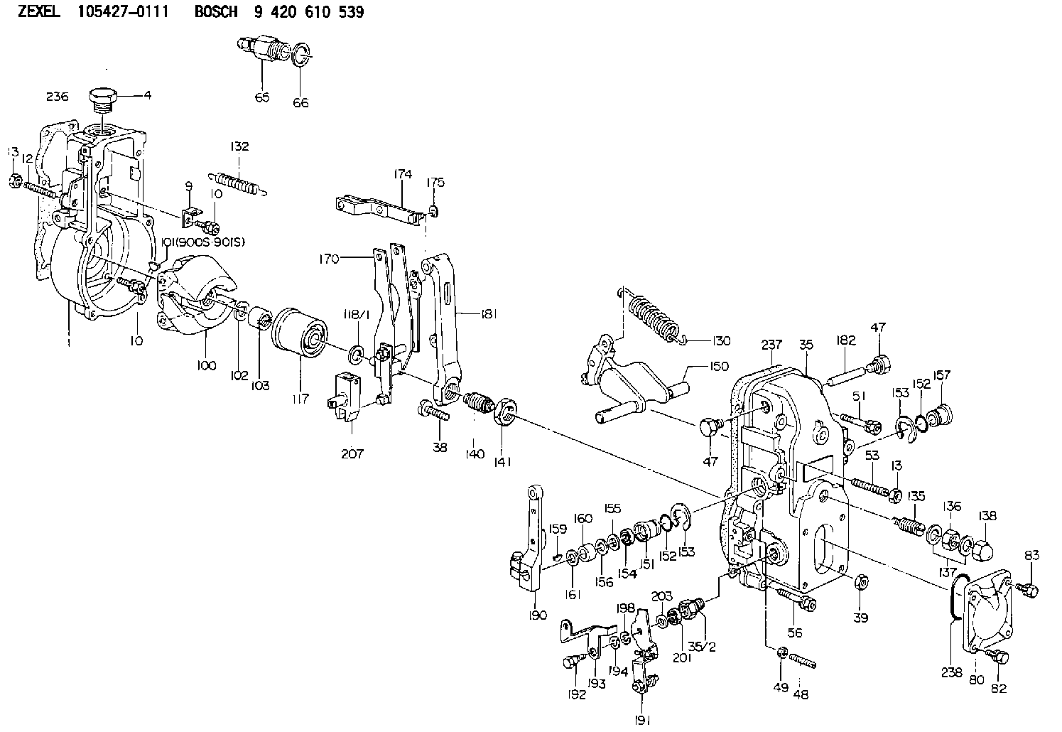
BOSCH
9 420 610 539
9420610539
ZEXEL
105427-0111
1054270111
Rating:
Scheme ###:
| 1. | [1] | 154000-4700 | GOVERNOR HOUSING |
| 4. | [1] | 154007-1600 | CAPSULE |
| 9. | [1] | 154350-6000 | PLATE |
| 10. | [8] | 020106-2040 | BLEEDER SCREW M6P1L20 |
| 10. | [8] | 020106-2040 | BLEEDER SCREW M6P1L20 |
| 12. | [1] | 154010-0100 | FLAT-HEAD SCREW |
| 13. | [2] | 154011-0100 | HEXAGON NUT |
| 13. | [2] | 154011-0100 | HEXAGON NUT |
| 35. | [1] | 154508-0320 | GOVERNOR COVER |
| 35/2. | [1] | 154321-1200 | BUSHING |
| 38. | [1] | 154031-0100 | FLAT-HEAD SCREW |
| 39. | [1] | 013020-6020 | UNION NUT M6P1H5 |
| 47. | [2] | 154036-0300 | CAPSULE |
| 47. | [2] | 154036-0300 | CAPSULE |
| 48. | [1] | 154037-0100 | FLAT-HEAD SCREW |
| 49. | [1] | 154038-0200 | HEXAGON NUT |
| 51. | [2] | 020106-5040 | BLEEDER SCREW |
| 53. | [1] | 154010-0500 | FLAT-HEAD SCREW |
| 56. | [4] | 020106-3840 | BLEEDER SCREW |
| 65. | [1] | 153021-8020 | STOPPING DEVICE |
| 66. | [1] | 026524-3040 | GASKET |
| 80. | [1] | 154060-7100 | COVER |
| 82. | [2] | 029020-6210 | BLEEDER SCREW |
| 83. | [2] | 020006-1640 | BLEEDER SCREW M6P1L16 4T |
| 100. | [1] | 154101-0520 | FLYWEIGHT ASSEMBLY |
| 101. | [1] | 025803-1310 | WOODRUFF KEY |
| 102. | [1] | 029321-2020 | LOCKING WASHER |
| 103. | [1] | 029231-2030 | UNION NUT |
| 117. | [1] | 154123-0120 | SLIDING PIECE |
| 118/1. | [0] | 029311-0010 | SHIM D14&10.1T0.2 |
| 118/1. | [0] | 029311-0180 | SHIM D14&10.1T0.3 |
| 118/1. | [0] | 029311-0190 | SHIM D14&10.1T0.40 |
| 118/1. | [0] | 029311-0210 | SHIM D14&10.1T1 |
| 118/1. | [0] | 139410-0000 | SHIM D14.0&10.1T0.5 |
| 118/1. | [0] | 139410-0100 | SHIM D14.0&10.1T1.5 |
| 118/1. | [0] | 139410-3000 | SHIM D14&10.1T2.0 |
| 118/1. | [0] | 139410-3100 | SHIM D14&10.1T3.0 |
| 118/1. | [0] | 139410-3200 | SHIM D14&10.1T4.0 |
| 130. | [1] | 154150-0400 | GOVERNOR SPRING |
| 132. | [1] | 154154-0701 | COILED SPRING |
| 135. | [1] | 154157-0120 | HEADLESS SCREW |
| 136. | [1] | 029201-2130 | UNION NUT M12P1.0H6 |
| 137. | [2] | 026512-1540 | GASKET D15.4&12.2T1.50 |
| 138. | [1] | 154159-0100 | CAP NUT |
| 140. | [1] | 154170-3320 | HEADLESS SCREW |
| 141. | [1] | 029201-6010 | UNION NUT |
| 150. | [1] | 154200-7020 | SWIVELLING LEVER |
| 151. | [1] | 154204-3000 | BUSHING |
| 152. | [2] | 029631-8020 | O-RING |
| 152. | [2] | 029631-8020 | O-RING |
| 153. | [2] | 016010-1640 | LOCKING WASHER |
| 153. | [2] | 016010-1640 | LOCKING WASHER |
| 154. | [1] | 139611-0000 | PACKING RING |
| 155. | [1] | 139411-0000 | SHIM |
| 156. | [0] | 029311-1070 | SHIM D16&11T0.5 |
| 157. | [1] | 154204-3100 | BUSHING |
| 159. | [1] | 025803-1310 | WOODRUFF KEY |
| 160. | [1] | 154206-2800 | BUSHING |
| 161. | [0] | 154206-0200 | PLAIN WASHER D19.5&11.2T1.0 |
| 170. | [1] | 154210-1220 | FORK LEVER |
| 174. | [1] | 154230-2920 | STRAP |
| 175. | [1] | 016010-0540 | LOCKING WASHER |
| 181. | [1] | 154236-4100 | TENSIONING LEVER |
| 182. | [1] | 154237-0100 | BEARING PIN |
| 190. | [1] | 154309-6120 | CONTROL LEVER |
| 191. | [1] | 154302-1220 | CONTROL LEVER |
| 192. | [1] | 154316-7000 | BLEEDER SCREW |
| 193. | [1] | 154301-6721 | CONTROL LEVER |
| 194. | [1] | 029300-6080 | PLAIN WASHER |
| 198. | [1] | 014110-6440 | LOCKING WASHER |
| 201. | [1] | 029621-0010 | PACKING RING |
| 203. | [0] | 029311-0220 | SHIM D18&10.3T0.2 |
| 203B. | [0] | 029311-0230 | SHIM D18&10.3T0.5 |
| 207. | [1] | 154326-5220 | CONTROL LEVER |
| 236. | [1] | 154371-5600 | GASKET |
| 237. | [1] | 154390-0300 | GASKET |
| 238. | [1] | 029635-2020 | O-RING |
| 900S. | [1] | 025803-1310 | WOODRUFF KEY |
| 901S. | [1] | 025803-1610 | WOODRUFF KEY |
Cross reference number
Zexel num
Bosch num
Firm num
Name
105427-0111
GOVERNOR
K 14JC MECHANICAL GOVERNOR GOV RSUV(D) GOV
K 14JC MECHANICAL GOVERNOR GOV RSUV(D) GOV
Information:
1. Remove oil filter element (1). 2. Remove two bolts (4).3. Remove four bolts (3).4. Remove six bolts (2). Remove oil filter base, gaskets and O-rings. The following steps are for the installation of the oil filter and oil filter base. Position gaskets and install all bolts finger tight before tightening to the standard torque.5. Be sure the O-rings are in place on oil filter base. Position gaskets and oil filter base. Install six bolts (2).6. Install four bolts (3).7. Position gasket. Install two bolts (4). Tighten all the bolts to standard torque.8. Install oil filter element (1).Disassemble & Assemble Oil Filter Base
Start By:a. remove oil filter base 1. Remove the O-rings. Remove bolt (1). 2. Remove relief valve group (2). 3. Remove four bolts and remove covers (3). Remove oil cooler by-pass valve (5), oil cooler by-pass valve spring (4) and spool (6). 4. Remove plug (7). Remove oil filter by-pass valve (8). The following steps are for the assembly of the oil filter base.5. Install by-pass valve (8) and plug (7).6. Install oil cooler by-pass valve (5), oil pump by-pass valve (6) and spring (4). Position covers (3). Install four bolts.7. Position relief valve group (2). Install bolt (1). Install O-ring seals.End By:a. install oil filter base
Start By:a. remove oil filter base 1. Remove the O-rings. Remove bolt (1). 2. Remove relief valve group (2). 3. Remove four bolts and remove covers (3). Remove oil cooler by-pass valve (5), oil cooler by-pass valve spring (4) and spool (6). 4. Remove plug (7). Remove oil filter by-pass valve (8). The following steps are for the assembly of the oil filter base.5. Install by-pass valve (8) and plug (7).6. Install oil cooler by-pass valve (5), oil pump by-pass valve (6) and spring (4). Position covers (3). Install four bolts.7. Position relief valve group (2). Install bolt (1). Install O-ring seals.End By:a. install oil filter base