Information governor
BOSCH
F 019 Z1E 608
f019z1e608
ZEXEL
105420-0720
1054200720
NISSAN-DIESEL
1910195008
1910195008
Rating:
Scheme ###:
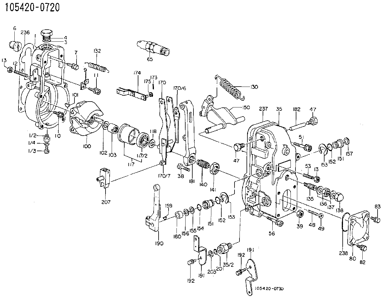
| 1. | [1] | 154000-3820 | GOVERNOR HOUSING |
| 1/1. | [1] | 154000-3800 | GOVERNOR HOUSING |
| 1/2. | [1] | 155012-0700 | ADAPTOR |
| 1/3. | [1] | 029010-6010 | CAPSULE M6P1.0L7 |
| 1/4. | [1] | 026506-1040 | GASKET D9.9&6.2T1 |
| 3. | [1] | 029632-5070 | O-RING |
| 4. | [1] | 154007-2900 | CAPSULE |
| 6. | [1] | 154007-0200 | ADAPTOR |
| 7. | [1] | 020018-1840 | BLEEDER SCREW M8P1.25L18 |
| 9. | [1] | 154350-1800 | PLATE |
| 10. | [5] | 029010-6810 | BLEEDER SCREW |
| 11. | [1] | 020106-1640 | BLEEDER SCREW M6P1.0L14 |
| 12. | [1] | 154010-0100 | FLAT-HEAD SCREW |
| 13. | [2] | 154011-0100 | HEXAGON NUT |
| 13. | [2] | 154011-0100 | HEXAGON NUT |
| 35. | [1] | 154508-0720 | GOVERNOR COVER |
| 35/2. | [1] | 154321-1200 | BUSHING |
| 38. | [1] | 154031-0100 | FLAT-HEAD SCREW |
| 39. | [1] | 013020-6020 | UNION NUT M6P1H5 |
| 47. | [2] | 154036-0300 | CAPSULE |
| 47. | [2] | 154036-0300 | CAPSULE |
| 48. | [1] | 154037-0100 | FLAT-HEAD SCREW |
| 49. | [1] | 154038-0200 | HEXAGON NUT |
| 51. | [2] | 020106-5040 | BLEEDER SCREW |
| 53. | [1] | 154010-0500 | FLAT-HEAD SCREW |
| 56. | [4] | 020106-3840 | BLEEDER SCREW |
| 65. | [1] | 154050-0320 | STOPPING DEVICE |
| 80. | [1] | 154060-7100 | COVER |
| 82. | [2] | 029020-6210 | BLEEDER SCREW |
| 83. | [2] | 020006-1640 | BLEEDER SCREW M6P1L16 4T |
| 100. | [1] | 154100-4020 | FLYWEIGHT ASSEMBLY |
| 101. | [1] | 025803-1610 | WOODRUFF KEY |
| 102. | [1] | 029321-2020 | LOCKING WASHER |
| 103. | [1] | 029231-2030 | UNION NUT |
| 117. | [1] | 154123-0120 | SLIDING PIECE |
| 118/1. | [0] | 029311-0010 | SHIM D14&10.1T0.2 |
| 118/1. | [0] | 029311-0180 | SHIM D14&10.1T0.3 |
| 118/1. | [0] | 029311-0190 | SHIM D14&10.1T0.40 |
| 118/1. | [0] | 029311-0210 | SHIM D14&10.1T1 |
| 118/1. | [0] | 139410-0000 | SHIM D14.0&10.1T0.5 |
| 118/1. | [0] | 139410-0100 | SHIM D14.0&10.1T1.5 |
| 118/1. | [0] | 139410-3000 | SHIM D14&10.1T2.0 |
| 118/1. | [0] | 139410-3100 | SHIM D14&10.1T3.0 |
| 118/1. | [0] | 139410-3200 | SHIM D14&10.1T4.0 |
| 130. | [1] | 154150-2700 | GOVERNOR SPRING |
| 132. | [1] | 154154-0701 | COILED SPRING |
| 135. | [1] | 154157-0120 | HEADLESS SCREW |
| 136. | [1] | 029201-2130 | UNION NUT M12P1.0H6 |
| 137. | [1] | 026512-1540 | GASKET D15.4&12.2T1.50 |
| 138. | [1] | 154159-0100 | CAP NUT |
| 140. | [1] | 154175-6120 | HEADLESS SCREW |
| 141. | [1] | 029201-6010 | UNION NUT |
| 150. | [1] | 154200-7120 | SWIVELLING LEVER |
| 151. | [1] | 154204-0102 | BUSHING |
| 151. | [1] | 154204-0102 | BUSHING |
| 152. | [2] | 029631-8020 | O-RING |
| 152. | [2] | 029631-8020 | O-RING |
| 153. | [2] | 016010-1640 | LOCKING WASHER |
| 153. | [2] | 016010-1640 | LOCKING WASHER |
| 154. | [1] | 029621-1010 | PACKING RING |
| 155. | [1] | 029311-1070 | SHIM D16&11T0.5 |
| 156. | [0] | 029311-1090 | SHIM D16&11T0.3 |
| 157. | [1] | 154204-4400 | BUSHING |
| 159. | [1] | 025803-1310 | WOODRUFF KEY |
| 160. | [1] | 154206-0100 | BUSHING |
| 170. | [1] | 154210-1220 | FORK LEVER |
| 173. | [1] | 025520-1210 | SPLIT PIN |
| 174. | [1] | 154230-0120 | STRAP |
| 181. | [1] | 154236-1500 | TENSIONING LEVER |
| 182. | [1] | 154237-0100 | BEARING PIN |
| 190. | [1] | 154309-6120 | CONTROL LEVER |
| 191. | [1] | 154304-6900 | CONTROL LEVER |
| 191. | [1] | 154304-6900 | CONTROL LEVER |
| 192. | [1] | 020006-1640 | BLEEDER SCREW M6P1L16 4T |
| 192. | [1] | 020006-1640 | BLEEDER SCREW M6P1L16 4T |
| 201. | [1] | 029621-0010 | PACKING RING |
| 203. | [0] | 029311-0220 | SHIM D18&10.3T0.2 |
| 203B. | [0] | 029311-0230 | SHIM D18&10.3T0.5 |
| 207. | [1] | 154326-5220 | CONTROL LEVER |
| 236. | [1] | 154390-0000 | GASKET |
| 237. | [1] | 154390-0300 | GASKET |
| 238. | [1] | 029635-2020 | O-RING |
Cross reference number
Zexel num
Bosch num
Firm num
Name
105420-0720
1910195008 NISSAN-DIESEL
GOVERNOR
* K 14JC MECHANICAL GOVERNOR GOV RSUV(D) GOV
* K 14JC MECHANICAL GOVERNOR GOV RSUV(D) GOV
Information:
Step 8. Check Signal Voltage At ECMA. Install the 40-Pin Breakout 'T' at the ECM Connector (J4/P4).B. Measure the voltage between Fuel Pressure, Pin 39 and Sensor Return Analog, Pin 35. The signal voltage should correspond to the observed fuel pressure reading shown in Table A. OK: The Fuel Pressure Signal is reaching the ECM. If Step 3 found that the ECM is not reading fuel pressure correctly, then the ECM is defective. Replace the ECM. Stop. NOT OK: The signal was good at the sensor but did not reach the ECM. Repair the wiring harness between Fuel Pressure Sensor and the ECM. Stop.P227: Retarder Enable Signal Test
The "Retarder Enable" signal is provided by the ECM to indicate that conditions are acceptable for an engine retarder to operate. Operation of the retarder is inhibited during undesirable engine operating conditions (such as while the engine is being fueled).With the Cruise Control ON/OFF Switch in the OFF position, the retarder is enabled under the following conditions:* engine rpm is greater than 950 rpm and* driver's foot is off the throttle pedal and the clutch pedalWith the Cruise Control ON/OFF Switch "ON", the operation of the retarder is also controlled through the customer parameter "Engine Retarder Mode". Programming the parameter to "COAST" allows retarding with the service brakes applied, but allows the engine to coast with no retarding after they are released. Programming the parameter to "LATCH" allows retarding with the service brake applied and keeps the retarder latched on after the service brakes are released (until engine rpm drops below 950 rpm or the driver presses the throttle or clutch pedal).The Retarder Enable Signal should be 15% Duty Cycle (nominal) to indicate that the retarder is enabled and 85% Duty Cycle (nominal) to indicate that it is disabled. The remainder of the engine retarder circuit is supplied by the OEM. In typical installations, the Retarder Enable signal isused by a separate Brake Control Module, which then energize the retarder solenoids. An "Engine Brake On" Switch is also typically connected to the Brake Control Module, and must be ON before the brake will operate. Step 1. Inspect Connectors And Wiring HarnessInspect the Vehicle Connector (J7/P7) and the ECM Connector (J4/P4) connections and wiring between, being sure to:* Check Connector lock rings.* Perform 10 pound pull test on each pin or wire.* Inspect wiring for damage or abrasion.* Inspect connectors for damage or corrosion. Refer to P-201: Inspecting Electrical Connectors for details. Repair any damage, then continue with the next step.Step 2. Verify Throttle Position And Clutch Switch InputsA. Use P-303: Throttle Position Sensor Adjustment procedure to verify correct adjustment of the throttle pedal. The "Throttle Position Signal" must be less than 7% at low idle, to perform the remainder of this test procedure.B. Use P-215: Service Brake And Clutch Switch Test, to verify correct adjustment and operation of the Clutch Pedal Switch. Clutch Switch Status must be OFF, with foot off the clutch, to perform the remainder of this test procedure.Step
The "Retarder Enable" signal is provided by the ECM to indicate that conditions are acceptable for an engine retarder to operate. Operation of the retarder is inhibited during undesirable engine operating conditions (such as while the engine is being fueled).With the Cruise Control ON/OFF Switch in the OFF position, the retarder is enabled under the following conditions:* engine rpm is greater than 950 rpm and* driver's foot is off the throttle pedal and the clutch pedalWith the Cruise Control ON/OFF Switch "ON", the operation of the retarder is also controlled through the customer parameter "Engine Retarder Mode". Programming the parameter to "COAST" allows retarding with the service brakes applied, but allows the engine to coast with no retarding after they are released. Programming the parameter to "LATCH" allows retarding with the service brake applied and keeps the retarder latched on after the service brakes are released (until engine rpm drops below 950 rpm or the driver presses the throttle or clutch pedal).The Retarder Enable Signal should be 15% Duty Cycle (nominal) to indicate that the retarder is enabled and 85% Duty Cycle (nominal) to indicate that it is disabled. The remainder of the engine retarder circuit is supplied by the OEM. In typical installations, the Retarder Enable signal isused by a separate Brake Control Module, which then energize the retarder solenoids. An "Engine Brake On" Switch is also typically connected to the Brake Control Module, and must be ON before the brake will operate. Step 1. Inspect Connectors And Wiring HarnessInspect the Vehicle Connector (J7/P7) and the ECM Connector (J4/P4) connections and wiring between, being sure to:* Check Connector lock rings.* Perform 10 pound pull test on each pin or wire.* Inspect wiring for damage or abrasion.* Inspect connectors for damage or corrosion. Refer to P-201: Inspecting Electrical Connectors for details. Repair any damage, then continue with the next step.Step 2. Verify Throttle Position And Clutch Switch InputsA. Use P-303: Throttle Position Sensor Adjustment procedure to verify correct adjustment of the throttle pedal. The "Throttle Position Signal" must be less than 7% at low idle, to perform the remainder of this test procedure.B. Use P-215: Service Brake And Clutch Switch Test, to verify correct adjustment and operation of the Clutch Pedal Switch. Clutch Switch Status must be OFF, with foot off the clutch, to perform the remainder of this test procedure.Step