Information governor
BOSCH
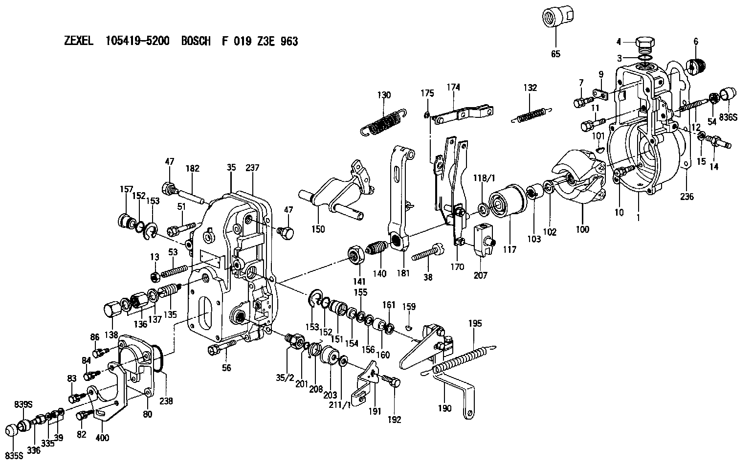
F 019 Z3E 963
f019z3e963
ZEXEL
105419-5200
1054195200
ISUZU
1157901880
1157901880
Rating:
Scheme ###:
| 1. | [1] | 154000-6400 | GOVERNOR HOUSING |
| 3. | [1] | 029632-5070 | O-RING |
| 4. | [1] | 154007-2900 | CAPSULE |
| 6. | [1] | 154007-0200 | ADAPTOR |
| 7. | [1] | 020018-1840 | BLEEDER SCREW M8P1.25L18 |
| 9. | [1] | 154350-1800 | PLATE |
| 10. | [5] | 029010-6810 | BLEEDER SCREW |
| 11. | [1] | 020106-1640 | BLEEDER SCREW M6P1.0L14 |
| 12. | [1] | 154013-5000 | FLAT-HEAD SCREW |
| 13. | [1] | 154011-0100 | HEXAGON NUT |
| 14. | [1] | 154013-2320 | BLEEDER SCREW |
| 15. | [1] | 014110-8440 | LOCKING WASHER |
| 35. | [1] | 154500-3020 | GOVERNOR COVER |
| 35/2. | [1] | 154321-0400 | BUSHING |
| 38. | [1] | 154031-2400 | FLAT-HEAD SCREW |
| 39. | [1] | 139206-0600 | UNION NUT |
| 47. | [2] | 154036-0300 | CAPSULE |
| 47. | [2] | 154036-0300 | CAPSULE |
| 51. | [2] | 020106-5040 | BLEEDER SCREW |
| 53. | [1] | 154010-0100 | FLAT-HEAD SCREW |
| 54. | [1] | 154011-4900 | UNION NUT |
| 56. | [4] | 020106-3840 | BLEEDER SCREW |
| 65. | [1] | 154050-6120 | STOPPING DEVICE |
| 80. | [1] | 154063-1400 | COVER |
| 82. | [1] | 020006-2040 | BLEEDER SCREW M6P1L20 4T |
| 83. | [1] | 020006-2040 | BLEEDER SCREW M6P1L20 4T |
| 84. | [1] | 029020-6260 | BLEEDER SCREW |
| 86. | [1] | 020006-1640 | BLEEDER SCREW M6P1L16 4T |
| 100. | [1] | 154101-0020 | FLYWEIGHT ASSEMBLY |
| 101. | [1] | 025803-1610 | WOODRUFF KEY |
| 102. | [1] | 029321-2020 | LOCKING WASHER |
| 103. | [1] | 029231-2030 | UNION NUT |
| 117. | [1] | 154123-0120 | SLIDING PIECE |
| 118/1. | [0] | 029311-0010 | SHIM D14&10.1T0.2 |
| 118/1. | [0] | 029311-0180 | SHIM D14&10.1T0.3 |
| 118/1. | [0] | 029311-0190 | SHIM D14&10.1T0.40 |
| 118/1. | [0] | 029311-0210 | SHIM D14&10.1T1 |
| 118/1. | [0] | 139410-0000 | SHIM D14.0&10.1T0.5 |
| 118/1. | [0] | 139410-0100 | SHIM D14.0&10.1T1.5 |
| 118/1. | [0] | 139410-3000 | SHIM D14&10.1T2.0 |
| 118/1. | [0] | 139410-3100 | SHIM D14&10.1T3.0 |
| 118/1. | [0] | 139410-3200 | SHIM D14&10.1T4.0 |
| 130. | [1] | 154150-4100 | GOVERNOR SPRING |
| 132. | [1] | 154154-0701 | COILED SPRING |
| 135. | [1] | 154158-0820 | HEADLESS SCREW |
| 136. | [1] | 154011-2700 | UNION NUT |
| 137. | [2] | 026512-1540 | GASKET D15.4&12.2T1.50 |
| 138. | [1] | 154159-1200 | CAP NUT |
| 140. | [1] | 154185-2120 | HEADLESS SCREW |
| 141. | [1] | 029201-6010 | UNION NUT |
| 150. | [1] | 154200-7220 | SWIVELLING LEVER |
| 151. | [1] | 154204-4300 | BUSHING |
| 152. | [2] | 139718-0600 | O-RING |
| 152. | [2] | 139718-0600 | O-RING |
| 153. | [2] | 016010-1640 | LOCKING WASHER |
| 153. | [2] | 016010-1640 | LOCKING WASHER |
| 154. | [1] | 139611-0400 | PACKING RING |
| 154. | [1] | 139611-0400 | PACKING RING |
| 155. | [1] | 139411-0000 | SHIM |
| 156. | [0] | 029311-1070 | SHIM D16&11T0.5 |
| 157. | [1] | 154204-4400 | BUSHING |
| 159. | [1] | 025803-1310 | WOODRUFF KEY |
| 160. | [1] | 154206-2800 | BUSHING |
| 161. | [0] | 154206-0200 | PLAIN WASHER D19.5&11.2T1.0 |
| 170. | [1] | 154210-7420 | FORK LEVER |
| 174. | [1] | 154230-3920 | STRAP |
| 175. | [1] | 016010-0540 | LOCKING WASHER |
| 181. | [1] | 154236-1500 | TENSIONING LEVER |
| 182. | [1] | 154237-0100 | BEARING PIN |
| 190. | [1] | 154395-6220 | CONTROL LEVER |
| 191. | [1] | 154304-8900 | CONTROL LEVER |
| 192. | [1] | 020006-1640 | BLEEDER SCREW M6P1L16 4T |
| 195. | [1] | 154314-2600 | COILED SPRING |
| 201. | [1] | 139710-0300 | O-RING |
| 203. | [1] | 154322-0100 | CAP |
| 207. | [1] | 154326-5120 | CONTROL LEVER |
| 208. | [1] | 154327-7300 | COILED SPRING |
| 211/1. | [0] | 029311-0520 | SHIM D20.8&10.3T0.2 |
| 211/1. | [0] | 029311-0530 | SHIM D20.8&10.3T0.25 |
| 211/1. | [0] | 029311-0540 | SHIM D20.8&10.3T0.3 |
| 211/1. | [0] | 029311-0550 | SHIM D20.8&10.3T0.35 |
| 211/1. | [0] | 029311-0560 | SHIM D20.8&10.3T0.4 |
| 211/1. | [0] | 029311-0570 | SHIM D20.8&10.3T0.5 |
| 236. | [1] | 154390-0000 | GASKET |
| 237. | [1] | 154390-0300 | GASKET |
| 238. | [1] | 139752-0000 | O-RING |
| 335. | [2] | 026506-1040 | GASKET D9.9&6.2T1 |
| 336. | [1] | 154035-2800 | CAP NUT |
| 400. | [1] | 154376-7100 | BRACKET |
| 835S. | [1] | 154062-4020 | CAP |
| 836S. | [1] | 154062-3520 | CAP |
| 839S. | [1] | 154062-3800 | ADAPTOR |
Include in #1:
101605-0350
as GOVERNOR
Cross reference number
Zexel num
Bosch num
Firm num
Name
105419-5200
1157901880 ISUZU
GOVERNOR
A K 14JB MECHANICAL GOVERNOR GOV RSV GOV
A K 14JB MECHANICAL GOVERNOR GOV RSV GOV
Information:
Start By:a. remove timing gear cover
Do not disconnect the air line from the air compressor governor until the air pressure is zero.
1. Loosen the bleed valves, and release the air pressure in the air tank. 2. Disconnect the lines from air compressor (1), and remove the air compressor. 3. Remove sleeve (2) from air compressor drive gear (3). 4. Remove the nut and washer that holds the air compressor drive gear to the air compressor. Use tooling (A) to remove air compressor drive gear (3) from the air compressor. 5. Remove nuts (4) and plate (5). Remove gear assembly (6) from the shaft. 6. If damaged, remove bearing (7) from gear assembly (6) with tooling (B) and a press. 7. Remove three nuts (8) and the washers from the adapter assembly studs. 8. Remove adapter assembly (9) from the timing gear plate. 9. Remove shaft (10), O-ring seal (11) and sleeve (12) from the adapter assembly.Install Air Compressor And Accessory Drive
1. Install sleeve (12) into the adapter assembly.2. Install shaft (10) and O-ring seal (11) on the adapter assembly. 3. Put adapter assembly (9) in position on the timing gear plate. fasten it with the three nuts and washers. 4. Install the bearing in gear assembly (6) with tooling (A) and a press. Install the bearing until it is 1.5 0.5 mm (.06 .02 in.) below the surface of the gear as shown. 5. Put gear assembly (6) in position on the shaft.6. Put plate (5) in position, and install three nuts (4) to hold it. 7. Put air compressor drive gear (3) in position on the air compressor shaft, and install the washer and nut (13). Tighten the nut to a torque of 200 25 N m (150 18 lb.ft.). Tap the gear with a hammer and tighten nut again to a torque of 200 25 N m (150 18 lb.ft 8. Install sleeve (2) on gear (3). 9. Put a gasket in position on air compressor (1) and install the air compressor on the timing cover plate.End By:a. install timing gear cover