Information governor
BOSCH
F 019 Z3E 716
f019z3e716
ZEXEL
105419-5090
1054195090
Rating:
Scheme ###:
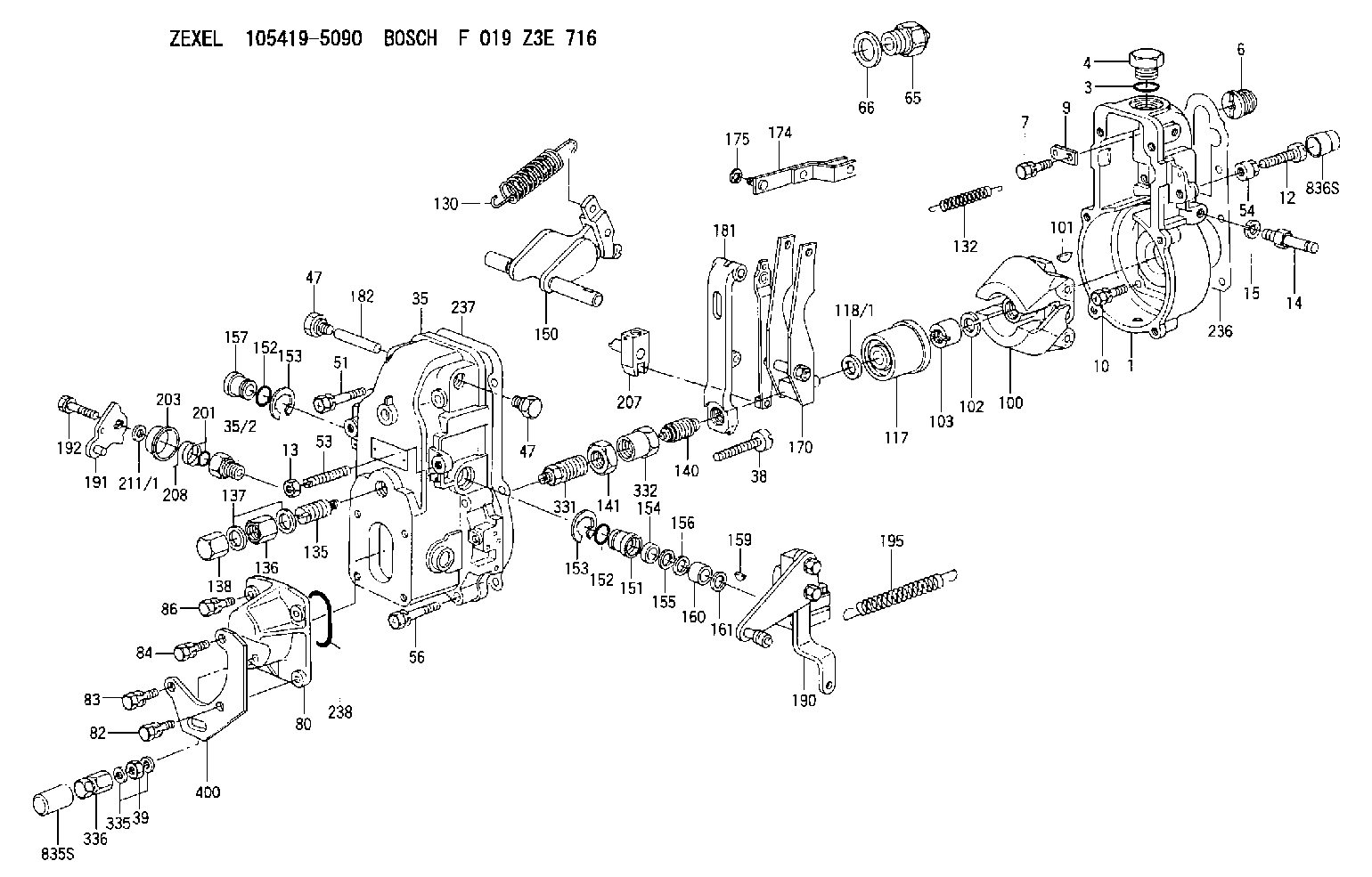
| 1. | [1] | 154000-6400 | GOVERNOR HOUSING |
| 3. | [1] | 029632-5070 | O-RING |
| 4. | [1] | 154007-2900 | CAPSULE |
| 6. | [1] | 154007-0200 | ADAPTOR |
| 7. | [1] | 020018-1840 | BLEEDER SCREW M8P1.25L18 |
| 9. | [1] | 154350-1900 | PLATE |
| 10. | [6] | 029010-6810 | BLEEDER SCREW |
| 12. | [1] | 154010-7200 | BLEEDER SCREW M8P1.25L62 |
| 12B. | [1] | 154010-8100 | BLEEDER SCREW M8P1.25L65 |
| 13. | [1] | 154011-0100 | HEXAGON NUT |
| 14. | [1] | 154013-2320 | BLEEDER SCREW |
| 15. | [1] | 014110-8440 | LOCKING WASHER |
| 35. | [1] | 154500-1020 | GOVERNOR COVER |
| 35/2. | [1] | 154321-0400 | BUSHING |
| 38. | [1] | 154031-3000 | FLAT-HEAD SCREW |
| 39. | [1] | 139206-0600 | UNION NUT |
| 47. | [2] | 154036-0300 | CAPSULE |
| 47. | [2] | 154036-0300 | CAPSULE |
| 51. | [2] | 020106-5040 | BLEEDER SCREW |
| 53. | [1] | 154010-0200 | FLAT-HEAD SCREW |
| 54. | [1] | 154011-2300 | UNION NUT |
| 56. | [4] | 020106-3840 | BLEEDER SCREW |
| 65. | [1] | 153020-5220 | STOPPING DEVICE |
| 66. | [1] | 026518-2240 | GASKET D21.9&18.2T1 |
| 80. | [1] | 154063-5100 | COVER |
| 82. | [1] | 029020-6260 | BLEEDER SCREW |
| 83. | [1] | 029020-6260 | BLEEDER SCREW |
| 84. | [1] | 020006-2040 | BLEEDER SCREW M6P1L20 4T |
| 86. | [1] | 020006-1640 | BLEEDER SCREW M6P1L16 4T |
| 100. | [1] | 154101-0020 | FLYWEIGHT ASSEMBLY |
| 101. | [1] | 025803-1610 | WOODRUFF KEY |
| 102. | [1] | 029321-2020 | LOCKING WASHER |
| 103. | [1] | 029231-2030 | UNION NUT |
| 117. | [1] | 154123-0120 | SLIDING PIECE |
| 118/1. | [0] | 029311-0010 | SHIM D14&10.1T0.2 |
| 118/1. | [0] | 029311-0180 | SHIM D14&10.1T0.3 |
| 118/1. | [0] | 029311-0190 | SHIM D14&10.1T0.40 |
| 118/1. | [0] | 029311-0210 | SHIM D14&10.1T1 |
| 118/1. | [0] | 139410-0000 | SHIM D14.0&10.1T0.5 |
| 118/1. | [0] | 139410-0100 | SHIM D14.0&10.1T1.5 |
| 118/1. | [0] | 139410-3000 | SHIM D14&10.1T2.0 |
| 118/1. | [0] | 139410-3100 | SHIM D14&10.1T3.0 |
| 118/1. | [0] | 139410-3200 | SHIM D14&10.1T4.0 |
| 130. | [1] | 154150-2900 | GOVERNOR SPRING |
| 132. | [1] | 154154-0701 | COILED SPRING |
| 135. | [1] | 154158-0920 | HEADLESS SCREW |
| 136. | [1] | 154011-1700 | UNION NUT |
| 137. | [2] | 026512-1540 | GASKET D15.4&12.2T1.50 |
| 138. | [1] | 154159-1200 | CAP NUT |
| 140. | [1] | 154185-6120 | HEADLESS SCREW |
| 141. | [1] | 029201-6080 | UNION NUT |
| 150. | [1] | 154200-6920 | SWIVELLING LEVER |
| 151. | [1] | 154204-4300 | BUSHING |
| 152. | [2] | 029631-8020 | O-RING |
| 152. | [2] | 029631-8020 | O-RING |
| 153. | [2] | 016010-1640 | LOCKING WASHER |
| 153. | [2] | 016010-1640 | LOCKING WASHER |
| 154. | [1] | 139611-0000 | PACKING RING |
| 155. | [1] | 139411-0000 | SHIM |
| 156. | [0] | 029311-1070 | SHIM D16&11T0.5 |
| 157. | [1] | 154204-4400 | BUSHING |
| 159. | [1] | 025803-1310 | WOODRUFF KEY |
| 160. | [1] | 154206-2800 | BUSHING |
| 161. | [0] | 154206-0200 | PLAIN WASHER D19.5&11.2T1.0 |
| 170. | [1] | 154216-3820 | FORK LEVER |
| 174. | [1] | 154230-3920 | STRAP |
| 175. | [1] | 016010-0540 | LOCKING WASHER |
| 181. | [1] | 154236-4100 | TENSIONING LEVER |
| 182. | [1] | 154237-0100 | BEARING PIN |
| 190. | [1] | 154396-3120 | CONTROL LEVER |
| 191. | [1] | 154382-7920 | CONTROL LEVER |
| 192. | [1] | 020006-1640 | BLEEDER SCREW M6P1L16 4T |
| 195. | [1] | 154314-2600 | COILED SPRING |
| 201. | [1] | 029631-0030 | O-RING &9.8W2.3 |
| 203. | [1] | 154322-0100 | CAP |
| 207. | [1] | 154326-5020 | CONTROL LEVER |
| 208. | [1] | 154327-7400 | COILED SPRING |
| 211/1. | [0] | 029311-0520 | SHIM D20.8&10.3T0.2 |
| 211/1. | [0] | 029311-0530 | SHIM D20.8&10.3T0.25 |
| 211/1. | [0] | 029311-0540 | SHIM D20.8&10.3T0.3 |
| 211/1. | [0] | 029311-0550 | SHIM D20.8&10.3T0.35 |
| 211/1. | [0] | 029311-0560 | SHIM D20.8&10.3T0.4 |
| 211/1. | [0] | 029311-0570 | SHIM D20.8&10.3T0.5 |
| 236. | [1] | 154390-0000 | GASKET |
| 237. | [1] | 154390-0300 | GASKET |
| 238. | [1] | 029635-2020 | O-RING |
| 331. | [1] | 154188-6220 | HEADLESS SCREW |
| 332. | [1] | 029201-6010 | UNION NUT |
| 335. | [2] | 026506-1040 | GASKET D9.9&6.2T1 |
| 336. | [1] | 154035-2500 | CAP NUT |
| 400. | [1] | 154358-7200 | BRACKET |
| 835S. | [1] | 154062-2000 | CAP D14L30.5 |
| 836S. | [1] | 154062-1700 | CAP D20L32 |
Include in #1:
101405-9450
as GOVERNOR
Cross reference number
Zexel num
Bosch num
Firm num
Name
Information:
1. Remove fuel line (1) from the fuel transfer pump.2. Put caps in the fuel line openings to prevent fuel system contamination.3. Remove bolts (2), and remove fuel transfer pump (3). Check the condition of the O-ring seal on the fuel transfer pump. If necessary, make a replacement. The following steps are for installation of the fuel transfer pump.4. Be sure the O-ring seal is in position on the fuel transfer pump. Put clean engine oil on the O-ring seal.5. Put fuel transfer pump (3) in position, and install the bolts that hold it in place.6. Remove the caps from the fuel line openings, and install fuel line (1).Disassemble Fuel Transfer Pump
Start By:a. remove fuel transfer pump 1. Remove seal (1) from the fuel transfer pump.
Cover (2) is under spring tension. Remove the bolts that hold cover (2) slowly to prevent injury.
2. Remove bolts (3) and cover (2) from the housing. 3. Remove seals (4) and valve (5) from cover (2). 4. Remove spring (6) from the piston.
Mark the orientation of valve (8) as to its location in the housing.
5. Remove washer (7), valve (8) and the seal from the housing. 6. Remove piston (9) and sleeve (10) from the housing. 7. Remove seal (11) from sleeve (12). 8. Remove guide and tappet assembly (13) from the housing. 9. Remove seal (14) from guide (15).
If tappet (17) or the guide are damaged or worn, they must be replaced as a unit.
10. Remove ring (16) from tappet (17) and the tappet from guide (15). 11. Remove the bolts and cover (18) from the housing. 12. Remove seal (19) from cover (18). 13. Remove valve (20) from the housing if necessary.Assemble Fuel Transfer Pump
1. Install valve (20) in housing as shown. 2. Put clean fuel on seal (19), and install it on cover (18).3. Install cover (18) on the housing.
The tappet and guide must be serviced as a unit.
4. Install tappet (17) in guide (15). Install ring (16) on tappet (17) to hold the tappet in the guide. 5. Put clean fuel on seal (14), and install it on guide and tappet assembly (13).6. Install guide and tappet assembly (13) in the housing as shown 7. Put clean fuel on seal (11), and install it on sleeve (12).8. Install sleeve (12) in the housing. 9. Install piston (9) in the housing. 10. Install seal, valve (8) and washer (7) in the housing as shown. Be sure valve (8) is the correct position in the housing. 11. Install spring (6) in the piston. 12. Install valve (5) in cover (2) as shown.13. Put clean fuel on seals (4), and put them in position on cover (2).14. Install cover (2) on the housing. 15. Put seal (1) in position on the fuel transfer pump.16. Install the fuel transfer pump on the fuel injection pump housing.End By:a. install fuel transfer pump