Information governor
BOSCH
F 019 Z3E 498
f019z3e498
ZEXEL
105419-4721
1054194721
Rating:
Scheme ###:
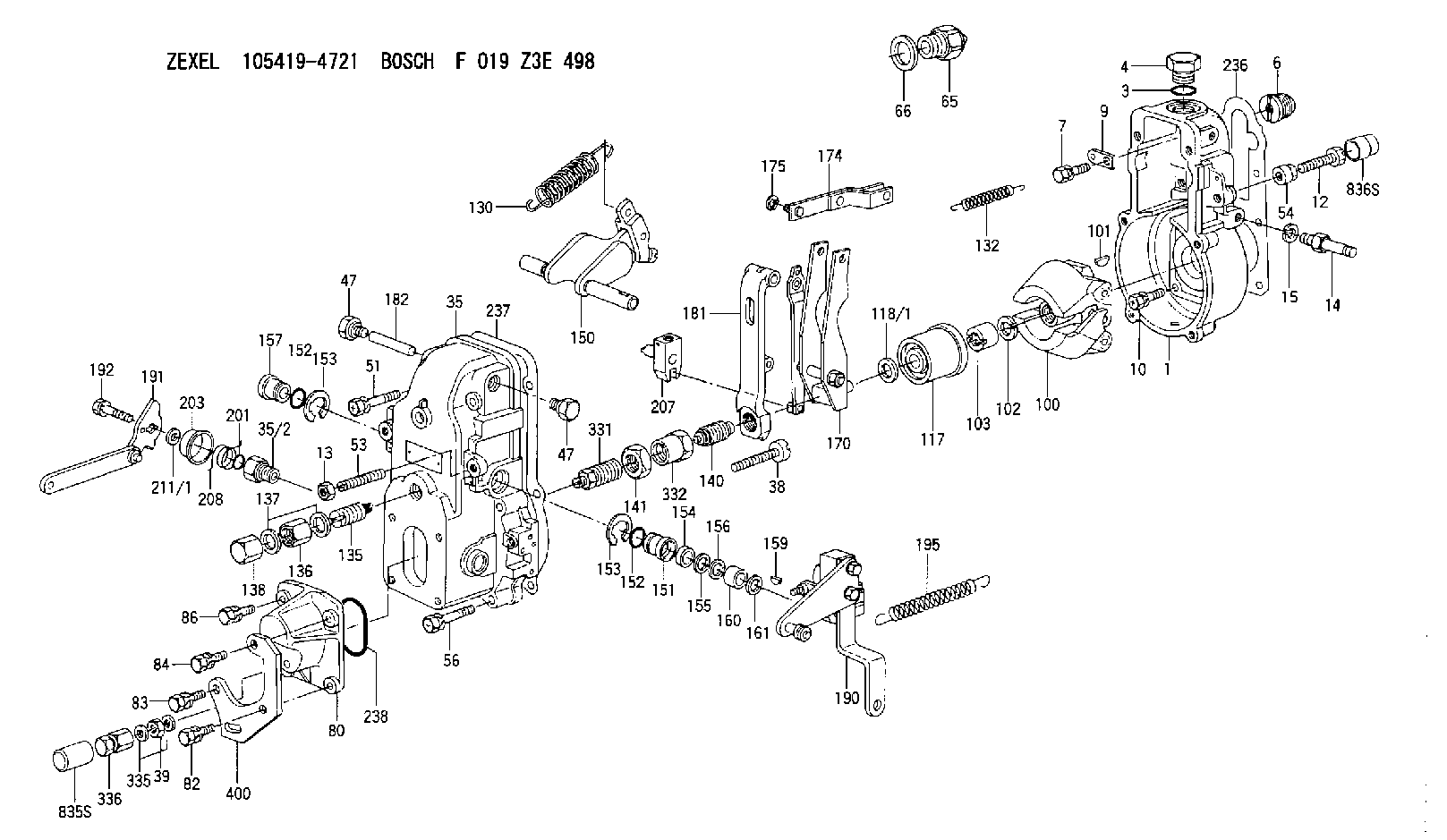
| 1. | [1] | 154000-6400 | GOVERNOR HOUSING |
| 3. | [1] | 029632-5070 | O-RING |
| 4. | [1] | 154007-2900 | CAPSULE |
| 6. | [1] | 154007-0200 | ADAPTOR |
| 7. | [1] | 020018-1840 | BLEEDER SCREW M8P1.25L18 |
| 9. | [1] | 154350-1900 | PLATE |
| 10. | [6] | 029010-6810 | BLEEDER SCREW |
| 12. | [1] | 154012-5500 | BLEEDER SCREW |
| 13. | [1] | 154011-0100 | HEXAGON NUT |
| 14. | [1] | 154013-2320 | BLEEDER SCREW |
| 15. | [1] | 014110-8440 | LOCKING WASHER |
| 35. | [1] | 154500-1020 | GOVERNOR COVER |
| 35/2. | [1] | 154321-0400 | BUSHING |
| 38. | [1] | 154031-3000 | FLAT-HEAD SCREW |
| 39. | [1] | 139206-0600 | UNION NUT |
| 47. | [2] | 154036-0300 | CAPSULE |
| 47. | [2] | 154036-0300 | CAPSULE |
| 51. | [2] | 020106-5040 | BLEEDER SCREW |
| 53. | [1] | 154010-0200 | FLAT-HEAD SCREW |
| 54. | [1] | 154011-2300 | UNION NUT |
| 56. | [4] | 020106-3840 | BLEEDER SCREW |
| 65. | [1] | 155404-5120 | STOPPING DEVICE |
| 66. | [1] | 026518-2240 | GASKET D21.9&18.2T1 |
| 80. | [1] | 154063-5100 | COVER |
| 82. | [1] | 029020-6260 | BLEEDER SCREW |
| 83. | [1] | 029020-6260 | BLEEDER SCREW |
| 84. | [1] | 020006-2040 | BLEEDER SCREW M6P1L20 4T |
| 86. | [1] | 020006-1640 | BLEEDER SCREW M6P1L16 4T |
| 100. | [1] | 154101-0020 | FLYWEIGHT ASSEMBLY |
| 101. | [1] | 025803-1610 | WOODRUFF KEY |
| 102. | [1] | 029321-2020 | LOCKING WASHER |
| 103. | [1] | 029231-2030 | UNION NUT |
| 117. | [1] | 154123-0120 | SLIDING PIECE |
| 118/1. | [0] | 029311-0010 | SHIM D14&10.1T0.2 |
| 118/1. | [0] | 029311-0180 | SHIM D14&10.1T0.3 |
| 118/1. | [0] | 029311-0190 | SHIM D14&10.1T0.40 |
| 118/1. | [0] | 029311-0210 | SHIM D14&10.1T1 |
| 118/1. | [0] | 139410-0000 | SHIM D14.0&10.1T0.5 |
| 118/1. | [0] | 139410-0100 | SHIM D14.0&10.1T1.5 |
| 118/1. | [0] | 139410-3000 | SHIM D14&10.1T2.0 |
| 118/1. | [0] | 139410-3100 | SHIM D14&10.1T3.0 |
| 118/1. | [0] | 139410-3200 | SHIM D14&10.1T4.0 |
| 130. | [1] | 154150-6400 | GOVERNOR SPRING |
| 132. | [1] | 154154-0701 | COILED SPRING |
| 135. | [1] | 154158-0920 | HEADLESS SCREW |
| 136. | [1] | 154011-1700 | UNION NUT |
| 137. | [2] | 026512-1540 | GASKET D15.4&12.2T1.50 |
| 138. | [1] | 154159-1200 | CAP NUT |
| 140. | [1] | 154185-4120 | HEADLESS SCREW |
| 141. | [1] | 029201-6080 | UNION NUT |
| 150. | [1] | 154200-6920 | SWIVELLING LEVER |
| 151. | [1] | 154204-4300 | BUSHING |
| 152. | [2] | 029631-8020 | O-RING |
| 152. | [2] | 029631-8020 | O-RING |
| 153. | [2] | 016010-1640 | LOCKING WASHER |
| 153. | [2] | 016010-1640 | LOCKING WASHER |
| 154. | [1] | 139611-0000 | PACKING RING |
| 155. | [1] | 139411-0000 | SHIM |
| 156. | [0] | 029311-1070 | SHIM D16&11T0.5 |
| 157. | [1] | 154204-4400 | BUSHING |
| 159. | [1] | 025803-1310 | WOODRUFF KEY |
| 160. | [1] | 154206-2800 | BUSHING |
| 161. | [0] | 154206-0200 | PLAIN WASHER D19.5&11.2T1.0 |
| 170. | [1] | 154216-3820 | FORK LEVER |
| 174. | [1] | 154230-3920 | STRAP |
| 175. | [1] | 016010-0540 | LOCKING WASHER |
| 181. | [1] | 154236-4100 | TENSIONING LEVER |
| 182. | [1] | 154237-0100 | BEARING PIN |
| 190. | [1] | 154395-6420 | CONTROL LEVER |
| 191. | [1] | 154383-4920 | CONTROL LEVER |
| 192. | [1] | 020006-1640 | BLEEDER SCREW M6P1L16 4T |
| 195. | [1] | 154314-2600 | COILED SPRING |
| 201. | [1] | 029631-0030 | O-RING &9.8W2.3 |
| 203. | [1] | 154322-0100 | CAP |
| 207. | [1] | 154326-5020 | CONTROL LEVER |
| 208. | [1] | 154327-7400 | COILED SPRING |
| 211/1. | [0] | 029311-0520 | SHIM D20.8&10.3T0.2 |
| 211/1. | [0] | 029311-0530 | SHIM D20.8&10.3T0.25 |
| 211/1. | [0] | 029311-0540 | SHIM D20.8&10.3T0.3 |
| 211/1. | [0] | 029311-0550 | SHIM D20.8&10.3T0.35 |
| 211/1. | [0] | 029311-0560 | SHIM D20.8&10.3T0.4 |
| 211/1. | [0] | 029311-0570 | SHIM D20.8&10.3T0.5 |
| 236. | [1] | 154390-0000 | GASKET |
| 237. | [1] | 154390-0300 | GASKET |
| 238. | [1] | 029635-2020 | O-RING |
| 331. | [1] | 154179-5520 | HEADLESS SCREW |
| 332. | [1] | 029201-6010 | UNION NUT |
| 335. | [2] | 026506-1040 | GASKET D9.9&6.2T1 |
| 336. | [1] | 154035-2500 | CAP NUT |
| 400. | [1] | 154358-7200 | BRACKET |
| 835S. | [1] | 154062-2000 | CAP D14L30.5 |
| 836S. | [1] | 154062-1700 | CAP D20L32 |
Cross reference number
Zexel num
Bosch num
Firm num
Name
Information:
Gauges provide indications of engine performance. Be sure they are in good working order. You can determine what is the "normal" operating range by observing the gauges over a period of time.Noticeable changes in gauge readings indicate potential gauge or engine problems. This also applies to gauge readings that have changed significantly, but are still within specifications. The cause of any sudden or significant change in gauge readings should be determined and corrected. Contact your Caterpillar dealer for assistance as needed.
Oil Pressure - Indicated engine oil pressure. The oil pressure should be greatest after starting a cold engine. Oil pressure should read between 275 and 606 kPa (40 and 88 psi) when: the engine is running at rated engine speed with SAE 10W30 oil, with an oil temperature no more than 110°C (230°F). A lower pressure is normal at low idling speed.If the oil pressure readings fluctuate after the load has stabilized:1. Remove the load.2. Reduce the engine speed to low idle.3. Check the oil level, and add oil if necessary.The minimum recommended oil pressure at 600 rpm is 103 kPa (15 psi). If low oil pressure or no oil pressure is indicated, stop the engine and determine the cause of the problem. Refer to the Troubleshooting section of the Service Manual, or consult with your Caterpillar dealer.
Engine damage can result if the engine is operated with no oil pressure gauge reading. If no pressure is indicated, stop the engine.
Jacket Water Temperature - Indicates engine coolant temperature. It should normally indicate between 87 to 98°C (189 to 209°F). Higher temperatures may occur under certain conditions. Maximum allowable temperature is 104°C (220°F) with the cooling system pressurized.If the engine is operating with a jacket water temperature above this range:1. Reduce the load and rpm.2. Look for coolant leaks.3. Determine if the engine must be shut down immediately, or if the engine can be cooled by reducing the load.
Ammeter - Indicates the amount of charge or discharge in the battery charging circuit. Normal operation of the indicator should be slightly to the positive (right) side of "0" (zero).Check the charging system for malfunction if, during operation, the indicator is constantly to the negative (left) side of "0" (zero) or shows excessive charge.
Tachometer - Indicates engine rpm (speed). The engine can be operated at high idle without damage, but should not be allowed to overspeed. Overspeeding can seriously damage your engine.
Do not exceed "bare engine high idle" rpm in any situation.
Fuel Level - Indicates fuel level in the fuel tank. The electrically operated fuel level gauge registers only when the START/STOP (ignition key) switch is ON.
Fuel Pressure - Indicates fuel pressure to the injection pump. The indicator should register in the NORMAL (green) range.If the indicator moves to the OUT position or registers below 160 kPa (23 psi) when equipped with a numerical gauge, the engine will not operate properly. In most cases this is caused by a plugged fuel filter.
Service Hour Meter - Indicates the total number of service meter