Information governor
BOSCH
F 019 Z2E 613
f019z2e613
ZEXEL
105419-4300
1054194300
ISUZU
8972544350
8972544350
Rating:
Scheme ###:
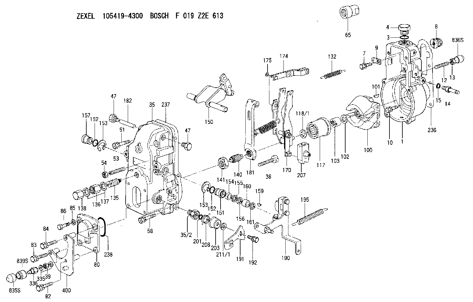
| 1. | [1] | 154000-6400 | GOVERNOR HOUSING |
| 3. | [1] | 029632-5070 | O-RING |
| 4. | [1] | 154007-2900 | CAPSULE |
| 6. | [1] | 154007-0200 | ADAPTOR |
| 7. | [1] | 020018-1840 | BLEEDER SCREW M8P1.25L18 |
| 9. | [1] | 154350-1900 | PLATE |
| 10. | [6] | 029010-6810 | BLEEDER SCREW |
| 12. | [1] | 154013-5000 | FLAT-HEAD SCREW |
| 13. | [1] | 154011-0100 | HEXAGON NUT |
| 14. | [1] | 154013-5120 | BLEEDER SCREW |
| 15. | [1] | 014110-8440 | LOCKING WASHER |
| 35. | [1] | 154500-3020 | GOVERNOR COVER |
| 35/2. | [1] | 154321-0400 | BUSHING |
| 38. | [1] | 154031-2400 | FLAT-HEAD SCREW |
| 39. | [1] | 139206-0600 | UNION NUT |
| 47. | [2] | 154036-0300 | CAPSULE |
| 47. | [2] | 154036-0300 | CAPSULE |
| 51. | [2] | 020106-5040 | BLEEDER SCREW |
| 53. | [1] | 154010-0200 | FLAT-HEAD SCREW |
| 54. | [1] | 154011-4900 | UNION NUT |
| 56. | [4] | 020106-3840 | BLEEDER SCREW |
| 65. | [1] | 154050-6120 | STOPPING DEVICE |
| 80. | [1] | 154064-4300 | COVER |
| 82. | [1] | 020006-5040 | BLEEDER SCREW M6P1.0L50 |
| 83. | [1] | 020006-5040 | BLEEDER SCREW M6P1.0L50 |
| 84. | [1] | 020506-5040 | BLEEDER SCREW M6P1L50 |
| 85. | [1] | 014110-6440 | LOCKING WASHER |
| 86. | [1] | 020006-1640 | BLEEDER SCREW M6P1L16 4T |
| 100. | [1] | 154101-0020 | FLYWEIGHT ASSEMBLY |
| 101. | [1] | 025803-1610 | WOODRUFF KEY |
| 102. | [1] | 029321-2020 | LOCKING WASHER |
| 103. | [1] | 029231-2030 | UNION NUT |
| 117. | [1] | 154123-0120 | SLIDING PIECE |
| 118/1. | [0] | 029311-0010 | SHIM D14&10.1T0.2 |
| 118/1. | [0] | 029311-0180 | SHIM D14&10.1T0.3 |
| 118/1. | [0] | 029311-0190 | SHIM D14&10.1T0.40 |
| 118/1. | [0] | 029311-0210 | SHIM D14&10.1T1 |
| 118/1. | [0] | 139410-0000 | SHIM D14.0&10.1T0.5 |
| 118/1. | [0] | 139410-0100 | SHIM D14.0&10.1T1.5 |
| 118/1. | [0] | 139410-3000 | SHIM D14&10.1T2.0 |
| 118/1. | [0] | 139410-3100 | SHIM D14&10.1T3.0 |
| 118/1. | [0] | 139410-3200 | SHIM D14&10.1T4.0 |
| 132. | [1] | 154154-0800 | COILED SPRING |
| 135. | [1] | 154158-0920 | HEADLESS SCREW |
| 136. | [1] | 154011-2700 | UNION NUT |
| 137. | [2] | 026512-1540 | GASKET D15.4&12.2T1.50 |
| 138. | [1] | 154159-1200 | CAP NUT |
| 140. | [1] | 154178-9220 | HEADLESS SCREW |
| 141. | [1] | 029201-6010 | UNION NUT |
| 150. | [1] | 154200-7220 | SWIVELLING LEVER |
| 151. | [1] | 154204-4300 | BUSHING |
| 152. | [2] | 139718-0600 | O-RING |
| 152. | [2] | 139718-0600 | O-RING |
| 153. | [2] | 016010-1640 | LOCKING WASHER |
| 153. | [2] | 016010-1640 | LOCKING WASHER |
| 154. | [1] | 139611-0400 | PACKING RING |
| 155. | [1] | 139411-0000 | SHIM |
| 156. | [0] | 029311-1070 | SHIM D16&11T0.5 |
| 157. | [1] | 154204-4400 | BUSHING |
| 159. | [1] | 025803-1310 | WOODRUFF KEY |
| 160. | [1] | 154206-2800 | BUSHING |
| 161. | [0] | 154206-0200 | PLAIN WASHER D19.5&11.2T1.0 |
| 170. | [1] | 154210-7420 | FORK LEVER |
| 174. | [1] | 154230-3920 | STRAP |
| 175. | [1] | 016010-0540 | LOCKING WASHER |
| 181. | [1] | 154239-1720 | TENSIONING LEVER |
| 182. | [1] | 154237-0100 | BEARING PIN |
| 190. | [1] | 154396-4820 | CONTROL LEVER |
| 191. | [1] | 154364-7800 | CONTROL LEVER |
| 192. | [1] | 020006-1640 | BLEEDER SCREW M6P1L16 4T |
| 195. | [1] | 154314-0200 | COILED SPRING |
| 201. | [1] | 139710-0300 | O-RING |
| 203. | [1] | 154322-0100 | CAP |
| 207. | [1] | 154326-5120 | CONTROL LEVER |
| 208. | [1] | 154327-7300 | COILED SPRING |
| 211/1. | [0] | 029311-0520 | SHIM D20.8&10.3T0.2 |
| 211/1. | [0] | 029311-0530 | SHIM D20.8&10.3T0.25 |
| 211/1. | [0] | 029311-0540 | SHIM D20.8&10.3T0.3 |
| 211/1. | [0] | 029311-0550 | SHIM D20.8&10.3T0.35 |
| 211/1. | [0] | 029311-0560 | SHIM D20.8&10.3T0.4 |
| 211/1. | [0] | 029311-0570 | SHIM D20.8&10.3T0.5 |
| 236. | [1] | 154390-0000 | GASKET |
| 237. | [1] | 154390-0300 | GASKET |
| 238. | [1] | 139752-0000 | O-RING |
| 335. | [2] | 026506-1040 | GASKET D9.9&6.2T1 |
| 336. | [1] | 154035-2800 | CAP NUT |
| 400. | [1] | 154376-5220 | BRACKET |
| 835S. | [1] | 154062-4020 | CAP |
| 836S. | [1] | 154062-3520 | CAP |
| 839S. | [1] | 154062-3800 | ADAPTOR |
Include in #1:
101402-7760
as GOVERNOR
Cross reference number
Zexel num
Bosch num
Firm num
Name
105419-4300
8972544350 ISUZU
GOVERNOR
K 14JB MECHANICAL GOVERNOR GOV RSV GOV
K 14JB MECHANICAL GOVERNOR GOV RSV GOV
Information:
Oil pressure should raise within nine seconds after the engine starts. If no oil pressure is indicated within ten seconds, the engine will shutdown. Investigate and correct the cause.
7. Do not apply load to the engine or increase engine rpm until the operating parameter readings indicate normal. Check all GSC display window readings during the warm-up period. Engine Starting Sequence
1. The GSC receives an engine start signal. The possible engine start signals are: a. ECS (Engine Control Switch) turned to MAN. START by the operatorb. The remote initiate contacts (IC) close while the ECS is in the AUTO position.2. The GSC checks the system before beginning the cranking sequence. The GSC checks that: a. No system faults are present.b. All previous faults have been reset (removed by turning the ECS to OFF/RESET).c. The engine is not already running.d. The service mode is not activated.3. The GSC activates the starting motor relay (SMR) and the run relay (RR).4. The GSC activates the fuel control relay (FCR) for the ETR fuel systems.5. The GSC cycle cranks (factory default is ten seconds crank and ten seconds rest) the engine until it starts or until the cycle crank time reaches the setpoint for total cycle crank time (overcrank).6. While the starting motor is cranking, the GSC shows the status of the relays on the relay status indicators of the lower display (i.e. K4, K5, K7 for ETR fuel systems).7. The GSC deactivates the starting motor relay (SMR) and activates the crank termination relay (CTR) when the engine speed reaches the setpoint for crank terminate speed (factory default is 400 rpm).8. The GSC activates the electronic governor (EG) relay when the oil pressure reaches the setpoint for low oil pressure at idle speed (factory default is 69 kPa [10 psi]). The EG relay signals the electronic governor (EG) to accelerate the engine to rated speed.9. The GSC shows: a. AC voltage, current, and frequency for one phase at a time on the upper display.b. System battery voltage, engine hours, engine rpm, oil pressure, and coolant temperature on the lower display.c. The relay status on the relay status indicators of the lower display. K1, K3, K5, K7 for ETR fuel systems.Starting From External Electrical Source
Make initial determination as to failure of engine to crank. Refer to special instruction SEHS7768 on use of 6V2150 Starting/Charging Analyzer Group.If the installation is not equipped with a back-up battery system, then it may be necessary to start the engine from an external electrical source. Many batteries thought to be unusable, are still rechargeable. Severely discharged maintenance free batteries might not fully recharge from the alternator alone after jump starting. The batteries must be charged to the proper voltage with a battery charger. Refer to Special Instruction, SEHS7633, Battery Test Procedure, available from your Caterpillar dealer, for complete testing and charging information.
Before attaching the booster cables, move ECS switch to OFF/RESET. Be sure the main power switch is in the OFF position before attaching the booster cables to