Information governor
BOSCH
9 420 614 841
9420614841
ZEXEL
105419-4050
1054194050
ISUZU
1157300840
1157300840
Rating:
Scheme ###:
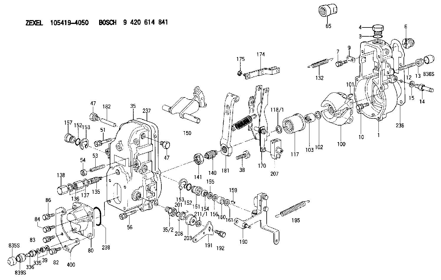
| 1. | [1] | 154000-6400 | GOVERNOR HOUSING |
| 3. | [1] | 029632-5070 | O-RING |
| 4. | [1] | 154007-2900 | CAPSULE |
| 6. | [1] | 154007-0200 | ADAPTOR |
| 7. | [1] | 020018-1840 | BLEEDER SCREW M8P1.25L18 |
| 9. | [1] | 154350-1900 | PLATE |
| 10. | [6] | 029010-6810 | BLEEDER SCREW |
| 12. | [1] | 154013-5000 | FLAT-HEAD SCREW |
| 13. | [1] | 154011-0100 | HEXAGON NUT |
| 14. | [1] | 154013-5120 | BLEEDER SCREW |
| 15. | [1] | 014110-8440 | LOCKING WASHER |
| 35. | [1] | 154500-3020 | GOVERNOR COVER |
| 35/2. | [1] | 154321-0400 | BUSHING |
| 38. | [1] | 154031-3000 | FLAT-HEAD SCREW |
| 39. | [1] | 139206-0600 | UNION NUT |
| 47. | [2] | 154036-0300 | CAPSULE |
| 47. | [2] | 154036-0300 | CAPSULE |
| 51. | [2] | 020106-5040 | BLEEDER SCREW |
| 53. | [1] | 154010-0200 | FLAT-HEAD SCREW |
| 54. | [1] | 154011-4900 | UNION NUT |
| 56. | [4] | 020106-3840 | BLEEDER SCREW |
| 65. | [1] | 154050-6120 | STOPPING DEVICE |
| 80. | [1] | 154063-5100 | COVER |
| 82. | [1] | 020006-2040 | BLEEDER SCREW M6P1L20 4T |
| 83. | [1] | 020006-2040 | BLEEDER SCREW M6P1L20 4T |
| 84. | [1] | 029020-6260 | BLEEDER SCREW |
| 86. | [1] | 020006-1640 | BLEEDER SCREW M6P1L16 4T |
| 100. | [1] | 154101-0120 | FLYWEIGHT |
| 101. | [1] | 025803-1610 | WOODRUFF KEY |
| 102. | [1] | 029321-2020 | LOCKING WASHER |
| 103. | [1] | 029231-2030 | UNION NUT |
| 117. | [1] | 154123-0120 | SLIDING PIECE |
| 118/1. | [0] | 029311-0010 | SHIM D14&10.1T0.2 |
| 118/1. | [0] | 029311-0180 | SHIM D14&10.1T0.3 |
| 118/1. | [0] | 029311-0190 | SHIM D14&10.1T0.40 |
| 118/1. | [0] | 029311-0210 | SHIM D14&10.1T1 |
| 118/1. | [0] | 139410-0000 | SHIM D14.0&10.1T0.5 |
| 118/1. | [0] | 139410-0100 | SHIM D14.0&10.1T1.5 |
| 118/1. | [0] | 139410-3000 | SHIM D14&10.1T2.0 |
| 118/1. | [0] | 139410-3100 | SHIM D14&10.1T3.0 |
| 118/1. | [0] | 139410-3200 | SHIM D14&10.1T4.0 |
| 132. | [1] | 154154-0800 | COILED SPRING |
| 135. | [1] | 154158-0920 | HEADLESS SCREW |
| 136. | [1] | 154011-2700 | UNION NUT |
| 137. | [2] | 026512-1540 | GASKET D15.4&12.2T1.50 |
| 138. | [1] | 154159-1200 | CAP NUT |
| 140. | [1] | 154185-4020 | HEADLESS SCREW |
| 141. | [1] | 029201-6010 | UNION NUT |
| 150. | [1] | 154200-6920 | SWIVELLING LEVER |
| 151. | [1] | 154204-4300 | BUSHING |
| 152. | [2] | 139718-0600 | O-RING |
| 152. | [2] | 139718-0600 | O-RING |
| 153. | [2] | 016010-1640 | LOCKING WASHER |
| 153. | [2] | 016010-1640 | LOCKING WASHER |
| 154. | [1] | 139611-0400 | PACKING RING |
| 155. | [1] | 139411-0000 | SHIM |
| 156. | [0] | 029311-1070 | SHIM D16&11T0.5 |
| 157. | [1] | 154204-4400 | BUSHING |
| 159. | [1] | 025803-1310 | WOODRUFF KEY |
| 160. | [1] | 154206-2800 | BUSHING |
| 161. | [0] | 154206-0200 | PLAIN WASHER D19.5&11.2T1.0 |
| 170. | [1] | 154210-0820 | FORK LEVER |
| 174. | [1] | 154230-3920 | STRAP |
| 175. | [1] | 016010-0540 | LOCKING WASHER |
| 181. | [1] | 154239-0520 | TENSIONING LEVER |
| 182. | [1] | 154237-0100 | BEARING PIN |
| 190. | [1] | 154396-4820 | CONTROL LEVER |
| 191. | [1] | 154307-4100 | CONTROL LEVER |
| 192. | [1] | 020006-1640 | BLEEDER SCREW M6P1L16 4T |
| 195. | [1] | 154314-0200 | COILED SPRING |
| 201. | [1] | 139710-0300 | O-RING |
| 203. | [1] | 154322-0100 | CAP |
| 207. | [1] | 154326-5120 | CONTROL LEVER |
| 208. | [1] | 154327-7300 | COILED SPRING |
| 211/1. | [0] | 029311-0520 | SHIM D20.8&10.3T0.2 |
| 211/1. | [0] | 029311-0530 | SHIM D20.8&10.3T0.25 |
| 211/1. | [0] | 029311-0540 | SHIM D20.8&10.3T0.3 |
| 211/1. | [0] | 029311-0550 | SHIM D20.8&10.3T0.35 |
| 211/1. | [0] | 029311-0560 | SHIM D20.8&10.3T0.4 |
| 211/1. | [0] | 029311-0570 | SHIM D20.8&10.3T0.5 |
| 236. | [1] | 154390-0000 | GASKET |
| 237. | [1] | 154390-0300 | GASKET |
| 238. | [1] | 139752-0000 | O-RING |
| 335. | [2] | 026506-1040 | GASKET D9.9&6.2T1 |
| 336. | [1] | 154035-2800 | CAP NUT |
| 400. | [1] | 154374-4300 | BRACKET |
| 835S. | [1] | 154062-4020 | CAP |
| 836S. | [1] | 154062-3520 | CAP |
| 839S. | [1] | 154062-3800 | ADAPTOR |
Include in #1:
101602-8960
as GOVERNOR
Cross reference number
Zexel num
Bosch num
Firm num
Name
105419-4050
1157300840 ISUZU
GOVERNOR
K 14JB MECHANICAL GOVERNOR GOV RSV GOV
K 14JB MECHANICAL GOVERNOR GOV RSV GOV
Information:
Raw/Sea Water Pump Failure
The raw/sea water pump circulates sea or fresh water through the engine jacket water heat exchanger. If the raw/sea water pump should fail, follow the procedure below to continue engine operation.
Shut off valve-normally closed (1), emergency raw/sea water pump (2), emergency raw/sea water inlet (3), inlet valve-normally closed (4), emergency raw/sea water strainers (5), normal operation raw/sea water strainers (6), normal operation raw/sea water inlet (7), inlet valve-normally open (8), raw/sea water pump (9), jacket water heat exchanger (10), raw/sea water outlet (11), and aftercooler (12).1. Stop the engine. If the shaft bearing has failed, the pump does NOT need to be removed.2. Close inlet valve (8) to raw/sea water strainers (6) and raw/sea water pump (9).3. Open inlet valve (4) to emergency raw/sea water pump (2). Start and prime the pump.4. Start the engine. Engage the marine gear and continue operation at normal speed.Engine Lube Oil Pump Failure
If the engine lube oil pump fails, the oil pressure will drop and the engine jacket water temperature gauge reading will be above normal. The applicable engine shutoff controls (if equipped) will stop the engine. Refer to the following procedure to use the emergency lube oil pump.1. Place the marine gear in the NEUTRAL position. Stop the engine (if the engine is still running).2. Measure the engine oil level. Ensure the oil level is between the ADD and FULL marks on the dipstick. Add oil if necessary.3. Reset the oil pressure shutoff control (if equipped). Be sure that the oil pressure shutoff control RESET is in the RUN position to enable engine starting.4. Start the emergency standby lube oil pump. Observe the oil pressure gauge5. Start the engine. Engage the marine gear and operate the vessel at normal speed.Turbocharger Failure
Air cleaner (1), turbocharger air inlet hose (2), compressor (3), clamp (4), cartridge (5), turbine housing (6), oil supply line (7), aftercooler air inlet hose (8), and oil drain line (9).1. Remove air cleaner (1) and turbocharger air inlet hose (2).2. Remove oil supply line (7) from the top of cartridge (5). Remove oil supply line (7) from the cylinder block. Plug the oil supply opening in the cylinder block.3. Remove oil drain line (9) from the bottom of cartridge (5). Remove oil drain line (9) from the flywheel housing. Plug the oil drain opening in the flyheel housing.4. Remove the bolts from the flange to aftercooler air inlet hose (8).5. Remove clamp (4) while supporting compressor (3) and aftercooler air inlet hose (8). Remove aftercooler air inlet hose (8), compressor (3) and cartridge (5) as a unit.
DO NOT allow exhaust gas to discharge into engine room. Vent the exhaust to the outside and be sure venting systems are correctly installed and operating. Diesel engine exhaust contains products of combustion which may be harmful to your health.
6. Provide some means of attaching a flat steel against the opening in turbine housing (6) where cartridge (5) was removed. The plate must be large enough to completely cover the opening.