Information governor
BOSCH
F 01G 29N 0FH
f01g29n0fh
ZEXEL
105419-3971
1054193971

Rating:
Scheme ###:
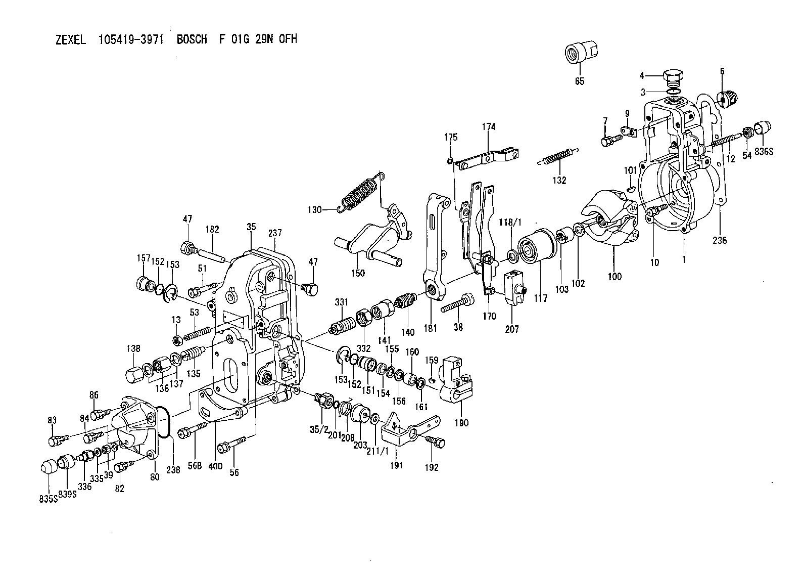
| 1. | [1] | 154000-6400 | GOVERNOR HOUSING |
| 3. | [1] | 029632-5070 | O-RING |
| 4. | [1] | 154007-2900 | CAPSULE |
| 6. | [1] | 154007-0200 | ADAPTOR |
| 7. | [1] | 020018-1840 | BLEEDER SCREW |
| 9. | [1] | 154350-1900 | PLATE |
| 10. | [6] | 029010-6810 | BLEEDER SCREW |
| 12. | [1] | 154013-4000 | FLAT-HEAD SCREW |
| 13. | [1] | 154011-0100 | HEXAGON NUT |
| 35. | [1] | 154500-3020 | GOVERNOR COVER |
| 35/2. | [1] | 154321-0400 | BUSHING |
| 38. | [1] | 154031-3000 | FLAT-HEAD SCREW |
| 39. | [1] | 139206-0600 | UNION NUT |
| 47. | [2] | 154036-0300 | CAPSULE |
| 47. | [2] | 154036-0300 | CAPSULE |
| 51. | [2] | 020106-5040 | BLEEDER SCREW |
| 53. | [1] | 154010-0100 | FLAT-HEAD SCREW |
| 54. | [1] | 154011-4900 | UNION NUT |
| 56. | [2] | 020106-3840 | BLEEDER SCREW |
| 56B. | [2] | 139006-8500 | BLEEDER SCREW |
| 65. | [1] | 154050-6120 | STOPPING DEVICE |
| 80. | [1] | 154064-0400 | COVER |
| 82. | [1] | 020006-1640 | BLEEDER SCREW |
| 83. | [1] | 020006-1640 | BLEEDER SCREW |
| 84. | [1] | 020006-1640 | BLEEDER SCREW |
| 86. | [1] | 020006-1640 | BLEEDER SCREW |
| 100. | [1] | 154101-0520 | FLYWEIGHT |
| 101. | [1] | 025803-1610 | WOODRUFF KEY 16 MM |
| 102. | [1] | 029321-2020 | LOCKING WASHER |
| 103. | [1] | 029231-2030 | UNION NUT |
| 117. | [1] | 154123-0120 | SLIDING PIECE |
| 118/1. | [0] | 029311-0010 | SHIM D14&10.1T0.2 |
| 118/1. | [0] | 029311-0180 | SHIM D14&10.1T0.3 |
| 118/1. | [0] | 029311-0190 | SHIM D14&10.1T0.40 |
| 118/1. | [0] | 029311-0210 | SHIM D14&10.1T1 |
| 118/1. | [0] | 139410-0000 | SHIM D14&10.1T0.5 |
| 118/1. | [0] | 139410-0100 | SHIM D14&10.1T1.5 |
| 118/1. | [0] | 139410-3000 | SHIM D14&10.1T2.0 |
| 118/1. | [0] | 139410-3100 | SHIM D14&10.1T3.0 |
| 118/1. | [0] | 139410-3200 | SHIM D14&10.1T4.0 |
| 130. | [1] | 154150-2700 | GOVERNOR SPRING |
| 132. | [1] | 154154-0500 | COILED SPRING |
| 135. | [1] | 154158-0920 | HEADLESS SCREW |
| 136. | [1] | 154011-1700 | UNION NUT |
| 137. | [2] | 026512-1540 | GASKET |
| 138. | [1] | 154159-1200 | CAP NUT |
| 140. | [1] | 154185-3620 | HEADLESS SCREW |
| 141. | [1] | 029201-6080 | UNION NUT |
| 150. | [1] | 154200-7220 | SWIVELLING LEVER |
| 151. | [1] | 154204-4300 | BUSHING |
| 152. | [2] | 029631-8020 | O-RING |
| 152. | [2] | 029631-8020 | O-RING |
| 153. | [2] | 016010-1640 | LOCKING WASHER |
| 153. | [2] | 016010-1640 | LOCKING WASHER |
| 154. | [1] | 139611-0000 | PACKING RING |
| 155. | [1] | 139411-0000 | SHIM |
| 156. | [0] | 029311-1070 | SHIM D16&11T0.5 |
| 157. | [1] | 154204-4400 | BUSHING |
| 159. | [1] | 025803-1310 | WOODRUFF KEY 13 MM |
| 160. | [1] | 154206-2800 | BUSHING |
| 161. | [0] | 154206-0200 | PLAIN WASHER D19.5&11.2T1.0 |
| 170. | [1] | 154210-7420 | FORK LEVER |
| 174. | [1] | 154230-3920 | STRAP |
| 175. | [1] | 016010-0540 | LOCKING WASHER |
| 181. | [1] | 154236-1500 | TENSIONING LEVER |
| 182. | [1] | 154237-0100 | BEARING PIN |
| 190. | [1] | 154340-2020 | CONTROL LEVER |
| 191. | [1] | 154381-7601 | CONTROL LEVER |
| 192. | [1] | 020006-1640 | BLEEDER SCREW |
| 201. | [1] | 029631-0030 | O-RING |
| 203. | [1] | 154322-0100 | CAP |
| 207. | [1] | 154326-5120 | CONTROL LEVER |
| 208. | [1] | 154327-9900 | COILED SPRING |
| 211/1. | [0] | 029311-0520 | SHIM D20.8&10.3T0.2 |
| 211/1. | [0] | 029311-0530 | SHIM D20.8&10.3T0.25 |
| 211/1. | [0] | 029311-0540 | SHIM D20.8&10.3T0.3 |
| 211/1. | [0] | 029311-0550 | SHIM D20.8&10.3T0.35 |
| 211/1. | [0] | 029311-0560 | SHIM D20.8&10.3T0.4 |
| 211/1. | [0] | 029311-0570 | SHIM D20.8&10.3T0.5 |
| 236. | [1] | 154390-0000 | GASKET |
| 237. | [1] | 154390-0300 | GASKET |
| 238. | [1] | 029635-2020 | O-RING |
| 331. | [1] | 154179-2220 | HEADLESS SCREW |
| 332. | [1] | 029201-6010 | UNION NUT |
| 335. | [2] | 026506-1040 | GASKET |
| 336. | [1] | 154035-2800 | CAP NUT |
| 400. | [1] | 154371-9620 | BRACKET |
| 835S. | [1] | 154062-4120 | CAP |
| 836S. | [1] | 154062-3520 | CAP |
| 839S. | [1] | 154062-3800 | ADAPTOR |
Include in #1:
101482-9341
as GOVERNOR
Cross reference number
Zexel num
Bosch num
Firm num
Name
Information:
You must read and understand the warnings and instructions contained in the Safety section of this manual before performing any operation or maintenance procedures.Before proceeding with PM Level 3 maintenance, perform all Daily, PM Level 1 and Level 2 maintenance requirements. The following maintenance procedures are to be performed Every 160 000 km (96,000 miles) or 4000 service hours or 4 years under ideal operating conditions, whichever occurs first.Refer to the Maintenance Schedule and Service Factor chart. Apply the correct Service Factor to determine the proper maintenance interval for your vehicle.Air Compressor
Inspect/Rebuild or Exchange
Do not disconnect the air line from the air compressor governor without purging the air brake and auxiliary air systems.Failure to purge the air brake and auxiliary air systems before removing the air compressor and/or air lines could cause personal injury.
Inspect the air compressor as instructed by the truck/vehicle manufacturers' instructions or for more information on how to check your air compressor, refer to the