Information governor
BOSCH
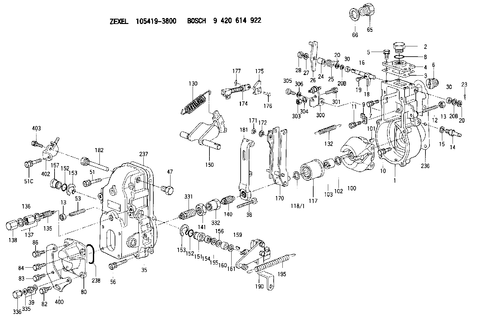
9 420 614 922
9420614922
ZEXEL
105419-3800
1054193800
Rating:
Scheme ###:
| 1. | [1] | 154004-5020 | GOVERNOR HOUSING |
| 2. | [1] | 154007-2900 | CAPSULE |
| 3. | [1] | 154390-2000 | GASKET |
| 4. | [1] | 154064-4500 | COVER |
| 5. | [4] | 020006-1640 | BLEEDER SCREW M6P1L16 4T |
| 6. | [1] | 154007-0200 | ADAPTOR |
| 7. | [1] | 020018-1840 | BLEEDER SCREW M8P1.25L18 |
| 8. | [1] | 029632-5070 | O-RING |
| 9. | [1] | 154350-1800 | PLATE |
| 10. | [5] | 029010-6810 | BLEEDER SCREW |
| 11. | [1] | 020106-1640 | BLEEDER SCREW M6P1.0L14 |
| 12. | [1] | 154010-0100 | FLAT-HEAD SCREW |
| 13. | [2] | 154011-0100 | HEXAGON NUT |
| 13. | [2] | 154011-0100 | HEXAGON NUT |
| 14. | [1] | 154013-2320 | BLEEDER SCREW |
| 15. | [1] | 014110-8440 | LOCKING WASHER |
| 16. | [1] | 155004-3301 | LEVER SHAFT |
| 18. | [1] | 155003-2520 | CONTROL LEVER |
| 19. | [1] | 155006-0700 | BLEEDER SCREW |
| 20. | [1] | 139308-0900 | PLAIN WASHER D16&8T1 |
| 20. | [1] | 139308-0900 | PLAIN WASHER D16&8T1 |
| 20B. | [1] | 139308-1000 | PLAIN WASHER D16&8T1.5 |
| 20B. | [1] | 139308-1000 | PLAIN WASHER D16&8T1.5 |
| 23. | [1] | 025520-1210 | SPLIT PIN |
| 24. | [1] | 154206-5200 | BUSHING |
| 25. | [1] | 154328-0500 | COILED SPRING |
| 26. | [1] | 154383-2420 | CONTROL LEVER |
| 27. | [1] | 014110-8440 | LOCKING WASHER |
| 28. | [1] | 013020-8040 | UNION NUT M8P1.25H7 |
| 30. | [2] | 029620-8050 | PACKING RING |
| 30. | [2] | 029620-8050 | PACKING RING |
| 35. | [1] | 154500-2020 | GOVERNOR COVER |
| 38. | [1] | 154031-3000 | FLAT-HEAD SCREW |
| 39. | [1] | 139206-0600 | UNION NUT |
| 47. | [1] | 154036-1200 | CAPSULE |
| 51. | [1] | 139006-7100 | BLEEDER SCREW |
| 51C. | [1] | 020106-5040 | BLEEDER SCREW |
| 53. | [1] | 154010-0100 | FLAT-HEAD SCREW |
| 56. | [4] | 020106-3840 | BLEEDER SCREW |
| 65. | [1] | 153020-5220 | STOPPING DEVICE |
| 66. | [1] | 026518-2240 | GASKET D21.9&18.2T1 |
| 80. | [1] | 154063-5100 | COVER |
| 82. | [1] | 029020-6260 | BLEEDER SCREW |
| 83. | [1] | 029020-6260 | BLEEDER SCREW |
| 84. | [1] | 020006-2040 | BLEEDER SCREW M6P1L20 4T |
| 86. | [1] | 020006-1640 | BLEEDER SCREW M6P1L16 4T |
| 100. | [1] | 154101-0020 | FLYWEIGHT ASSEMBLY |
| 101. | [1] | 025803-1610 | WOODRUFF KEY |
| 102. | [1] | 029321-2020 | LOCKING WASHER |
| 103. | [1] | 029231-2030 | UNION NUT |
| 117. | [1] | 154123-0120 | SLIDING PIECE |
| 118/1. | [0] | 029311-0010 | SHIM D14&10.1T0.2 |
| 118/1. | [0] | 029311-0180 | SHIM D14&10.1T0.3 |
| 118/1. | [0] | 029311-0190 | SHIM D14&10.1T0.40 |
| 118/1. | [0] | 029311-0210 | SHIM D14&10.1T1 |
| 118/1. | [0] | 139410-0000 | SHIM D14.0&10.1T0.5 |
| 118/1. | [0] | 139410-0100 | SHIM D14.0&10.1T1.5 |
| 118/1. | [0] | 139410-3000 | SHIM D14&10.1T2.0 |
| 118/1. | [0] | 139410-3100 | SHIM D14&10.1T3.0 |
| 118/1. | [0] | 139410-3200 | SHIM D14&10.1T4.0 |
| 130. | [1] | 154150-2900 | GOVERNOR SPRING |
| 132. | [1] | 154154-0701 | COILED SPRING |
| 135. | [1] | 154158-0920 | HEADLESS SCREW |
| 136. | [1] | 154011-1700 | UNION NUT |
| 137. | [2] | 026512-1540 | GASKET D15.4&12.2T1.50 |
| 138. | [1] | 154159-1200 | CAP NUT |
| 140. | [1] | 154185-6120 | HEADLESS SCREW |
| 141. | [1] | 029201-6080 | UNION NUT |
| 150. | [1] | 154200-6920 | SWIVELLING LEVER |
| 151. | [1] | 154204-4300 | BUSHING |
| 152. | [2] | 029631-8020 | O-RING |
| 152. | [2] | 029631-8020 | O-RING |
| 153. | [2] | 016010-1640 | LOCKING WASHER |
| 153. | [2] | 016010-1640 | LOCKING WASHER |
| 154. | [1] | 139611-0000 | PACKING RING |
| 155. | [1] | 139411-0000 | SHIM |
| 156. | [0] | 029311-1070 | SHIM D16&11T0.5 |
| 157. | [1] | 154204-4400 | BUSHING |
| 159. | [1] | 025803-1310 | WOODRUFF KEY |
| 160. | [1] | 154206-2800 | BUSHING |
| 161. | [0] | 154206-0200 | PLAIN WASHER D19.5&11.2T1.0 |
| 170. | [1] | 154218-0120 | FORK LEVER |
| 171. | [1] | 016010-0540 | LOCKING WASHER |
| 172. | [4] | 029310-5170 | SHIM D8&5.3T0.5 |
| 174. | [1] | 154234-4020 | STRAP |
| 175. | [1] | 154232-3000 | CONNECTOR |
| 176. | [1] | 154222-5800 | BEARING PIN |
| 177. | [1] | 155402-3800 | SAFETY PIN |
| 181. | [1] | 154236-4100 | TENSIONING LEVER |
| 182. | [1] | 154237-1100 | BEARING PIN |
| 190. | [1] | 154396-3120 | CONTROL LEVER |
| 195. | [1] | 154314-2600 | COILED SPRING |
| 236. | [1] | 154390-0000 | GASKET |
| 237. | [1] | 154390-0300 | GASKET |
| 238. | [1] | 029635-2020 | O-RING |
| 300. | [1] | 154359-1320 | BRACKET |
| 301. | [1] | 020118-1640 | BLEEDER SCREW |
| 303. | [1] | 154011-1100 | UNION NUT |
| 304. | [1] | 029300-8320 | SHIM |
| 305. | [1] | 154010-6100 | BLEEDER SCREW |
| 306. | [1] | 014110-8440 | LOCKING WASHER |
| 331. | [1] | 154179-7220 | HEADLESS SCREW |
| 332. | [1] | 029201-6010 | UNION NUT |
| 335. | [2] | 026506-1040 | GASKET D9.9&6.2T1 |
| 336. | [1] | 154035-1600 | CAP NUT |
| 400. | [1] | 154376-3000 | BRACKET |
| 402. | [1] | 154376-3120 | BRACKET |
| 403. | [1] | 020006-1240 | BLEEDER SCREW M6P1L12 4T |
Include in #1:
101402-9920
as GOVERNOR
Cross reference number
Zexel num
Bosch num
Firm num
Name
Information:
Crankshaft Vibration Damper
Inspect/Check
Damage to, or failure of, the damper will increase torsional vibrations and result in damage to the crankshaft and other engine components. A deteriorating vibration damper will cause excessive gear train noise at variable points in the speed range.Visconic Damper (If Equipped)
The vibration damper weight is located inside a fluid filled case. The weight moves in the case to limit torsional vibration. Inspect the dampers for evidence of dents, cracks or leaks of the fluid.Rubber Damper (If Equipped)
The vibration damper can have a visual wobble (movement to the front and rear when in rotation) on the outer ring. This does not mean a replacement is necessary since some wobble of the outer ring is normal. To see if the amount of wobble is acceptable, or replacement is necessary, check the damper with the procedure in the Testing and Adjusting section of the Service Manual.The vibration damper has marks on the hub and ring. These marks will indicate the condition of the vibration damper. If the marks are not in alignment, the rubber seal between the ring and the hub has separated from the ring and/or hub. If the marks are not in alignment, install a new vibration damper. Refer to the Service Manual for the necessary replacement procedure.Air Compressor
Inspect/Check
Do not disconnect the air line from the air compressor governor without purging the air brake and auxiliary air systems.Failure to purge the air brake and auxiliary air systems before removing the air compressor could cause personal injury.
Inspect the air compressor as instructed by the OEM truck manufacturers' instructions or for more information on how to check your air compressor, refer to the Service Manual for this engine.If you decide to inspect your air compressor, be sure to observe the following actions. Visually check for fluid leaks and listen for air leaks. Release the air pressure in the air tank until the air pressure is zero. Visually check for fluid leaks. Remove discharge fittings and inspect compressor discharge port and discharge line for excessive carbon deposits. The discharge line must be cleaned or replaced and the compressor checked more thoroughly if there is excessive carbon build-up in either the discharge line or compressor discharge port.For more information on how to check your air compressor, refer to the OEM truck manufacturer's instructions or engine Service Manual.Engine Valve Lash
The procedures for engine valve lash should be performed according to the information in the Service Manual.
Check/Adjust
Be sure the engine cannot be started while this maintenance is being performed. To prevent possible injury, do not use the starting motor to turn the flywheel.Hot engine components can cause burns. Allow additional time for the engine to cool before measuring/adjusting valve lash.The 3176 uses high voltage to the unit injectors. Disconnect injector enable circuit connector J5/P5 to prevent personal injury. Do not come in contact with the injector terminals while the engine is running.
Adjust the valve lash to the setting given in the chart above.Refer to the Service Manual or your Caterpillar dealer for
Inspect/Check
Damage to, or failure of, the damper will increase torsional vibrations and result in damage to the crankshaft and other engine components. A deteriorating vibration damper will cause excessive gear train noise at variable points in the speed range.Visconic Damper (If Equipped)
The vibration damper weight is located inside a fluid filled case. The weight moves in the case to limit torsional vibration. Inspect the dampers for evidence of dents, cracks or leaks of the fluid.Rubber Damper (If Equipped)
The vibration damper can have a visual wobble (movement to the front and rear when in rotation) on the outer ring. This does not mean a replacement is necessary since some wobble of the outer ring is normal. To see if the amount of wobble is acceptable, or replacement is necessary, check the damper with the procedure in the Testing and Adjusting section of the Service Manual.The vibration damper has marks on the hub and ring. These marks will indicate the condition of the vibration damper. If the marks are not in alignment, the rubber seal between the ring and the hub has separated from the ring and/or hub. If the marks are not in alignment, install a new vibration damper. Refer to the Service Manual for the necessary replacement procedure.Air Compressor
Inspect/Check
Do not disconnect the air line from the air compressor governor without purging the air brake and auxiliary air systems.Failure to purge the air brake and auxiliary air systems before removing the air compressor could cause personal injury.
Inspect the air compressor as instructed by the OEM truck manufacturers' instructions or for more information on how to check your air compressor, refer to the Service Manual for this engine.If you decide to inspect your air compressor, be sure to observe the following actions. Visually check for fluid leaks and listen for air leaks. Release the air pressure in the air tank until the air pressure is zero. Visually check for fluid leaks. Remove discharge fittings and inspect compressor discharge port and discharge line for excessive carbon deposits. The discharge line must be cleaned or replaced and the compressor checked more thoroughly if there is excessive carbon build-up in either the discharge line or compressor discharge port.For more information on how to check your air compressor, refer to the OEM truck manufacturer's instructions or engine Service Manual.Engine Valve Lash
The procedures for engine valve lash should be performed according to the information in the Service Manual.
Check/Adjust
Be sure the engine cannot be started while this maintenance is being performed. To prevent possible injury, do not use the starting motor to turn the flywheel.Hot engine components can cause burns. Allow additional time for the engine to cool before measuring/adjusting valve lash.The 3176 uses high voltage to the unit injectors. Disconnect injector enable circuit connector J5/P5 to prevent personal injury. Do not come in contact with the injector terminals while the engine is running.
Adjust the valve lash to the setting given in the chart above.Refer to the Service Manual or your Caterpillar dealer for