Information governor
BOSCH
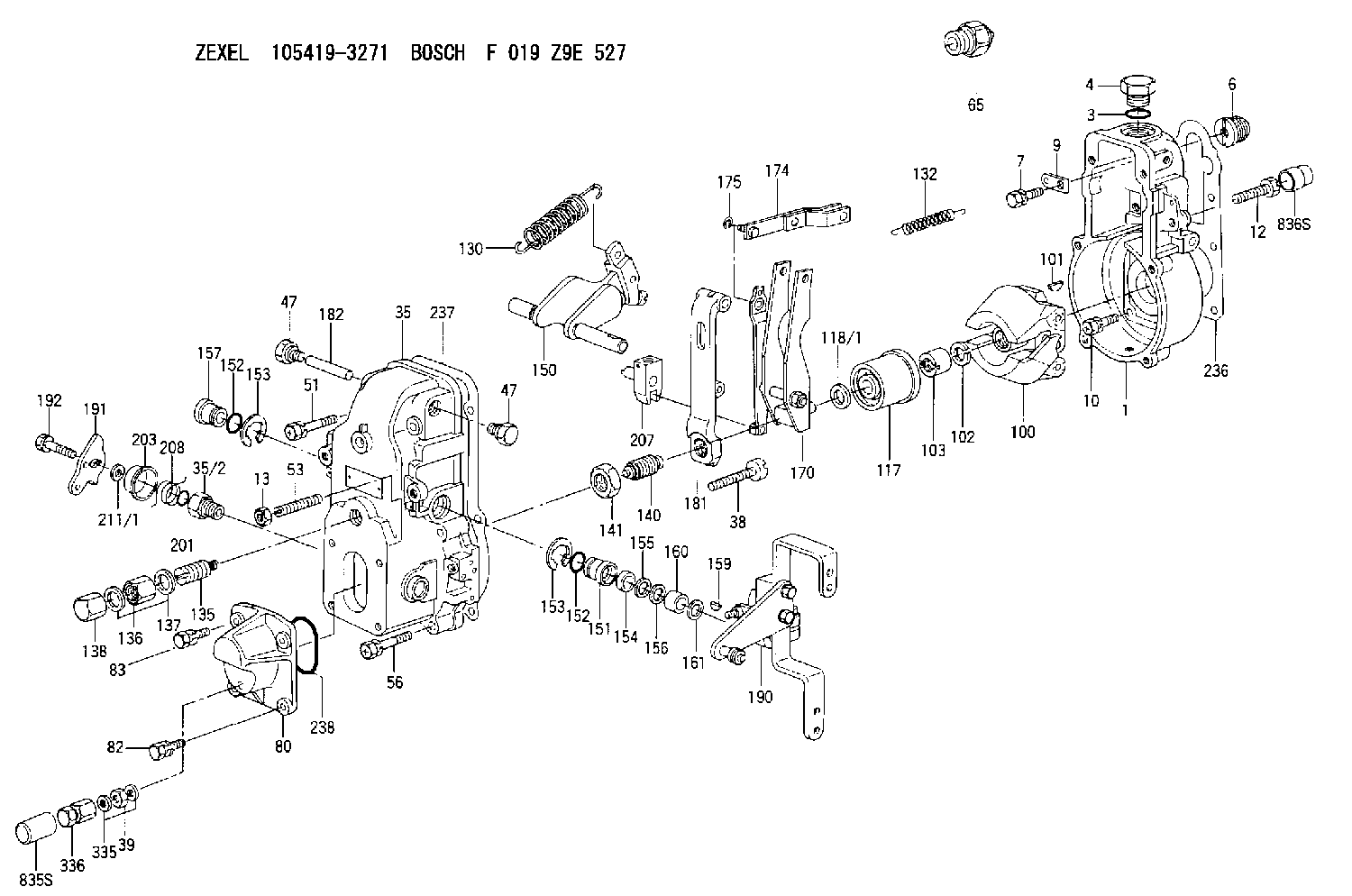
F 019 Z9E 527
f019z9e527
ZEXEL
105419-3271
1054193271
Rating:
Scheme ###:
| 1. | [1] | 154000-6400 | GOVERNOR HOUSING |
| 3. | [1] | 029632-5070 | O-RING |
| 4. | [1] | 154007-2900 | CAPSULE |
| 6. | [1] | 154007-0200 | ADAPTOR |
| 7. | [1] | 020018-1840 | BLEEDER SCREW M8P1.25L18 |
| 9. | [1] | 154350-1900 | PLATE |
| 10. | [6] | 029010-6810 | BLEEDER SCREW |
| 12. | [1] | 154010-1200 | FLAT-HEAD SCREW |
| 13. | [2] | 154011-0100 | HEXAGON NUT |
| 35. | [1] | 154500-5320 | GOVERNOR COVER |
| 35/2. | [1] | 154321-0400 | BUSHING |
| 38. | [1] | 154031-2400 | FLAT-HEAD SCREW |
| 39. | [1] | 139206-0600 | UNION NUT |
| 47. | [2] | 154036-0300 | CAPSULE |
| 47. | [2] | 154036-0300 | CAPSULE |
| 51. | [2] | 020106-5040 | BLEEDER SCREW |
| 53. | [1] | 154010-1100 | FLAT-HEAD SCREW |
| 56. | [4] | 020106-3840 | BLEEDER SCREW |
| 65. | [1] | 154050-6120 | STOPPING DEVICE |
| 80. | [1] | 154063-5420 | COVER |
| 82. | [2] | 029020-6210 | BLEEDER SCREW |
| 83. | [2] | 020006-1640 | BLEEDER SCREW M6P1L16 4T |
| 100. | [1] | 154101-0120 | FLYWEIGHT |
| 101. | [1] | 025803-1610 | WOODRUFF KEY |
| 102. | [1] | 029321-2020 | LOCKING WASHER |
| 103. | [1] | 029231-2030 | UNION NUT |
| 117. | [1] | 154123-2320 | SLIDING PIECE |
| 118/1. | [0] | 029311-0010 | SHIM D14&10.1T0.2 |
| 118/1. | [0] | 029311-0180 | SHIM D14&10.1T0.3 |
| 118/1. | [0] | 029311-0190 | SHIM D14&10.1T0.40 |
| 118/1. | [0] | 029311-0210 | SHIM D14&10.1T1 |
| 118/1. | [0] | 139410-0000 | SHIM D14.0&10.1T0.5 |
| 118/1. | [0] | 139410-0100 | SHIM D14.0&10.1T1.5 |
| 118/1. | [0] | 139410-3000 | SHIM D14&10.1T2.0 |
| 118/1. | [0] | 139410-3100 | SHIM D14&10.1T3.0 |
| 118/1. | [0] | 139410-3200 | SHIM D14&10.1T4.0 |
| 130. | [1] | 154150-6400 | GOVERNOR SPRING |
| 132. | [1] | 154154-0500 | COILED SPRING |
| 135. | [1] | 154158-0820 | HEADLESS SCREW |
| 136. | [1] | 154011-1700 | UNION NUT |
| 137. | [2] | 026512-1540 | GASKET D15.4&12.2T1.50 |
| 138. | [1] | 154159-1200 | CAP NUT |
| 140. | [1] | 154177-0920 | HEADLESS SCREW |
| 141. | [1] | 029201-6010 | UNION NUT |
| 150. | [1] | 154200-6920 | SWIVELLING LEVER |
| 151. | [1] | 154204-4300 | BUSHING |
| 152. | [2] | 029631-8020 | O-RING |
| 152. | [2] | 029631-8020 | O-RING |
| 153. | [2] | 016010-1640 | LOCKING WASHER |
| 153. | [2] | 016010-1640 | LOCKING WASHER |
| 154. | [1] | 139611-0000 | PACKING RING |
| 155. | [1] | 139411-0000 | SHIM |
| 156. | [0] | 029311-1070 | SHIM D16&11T0.5 |
| 157. | [1] | 154204-4400 | BUSHING |
| 159. | [1] | 025803-1310 | WOODRUFF KEY |
| 160. | [1] | 154206-2800 | BUSHING |
| 161. | [0] | 154206-0200 | PLAIN WASHER D19.5&11.2T1.0 |
| 170. | [1] | 154210-0820 | FORK LEVER |
| 174. | [1] | 154230-3920 | STRAP |
| 175. | [1] | 016010-0540 | LOCKING WASHER |
| 181. | [1] | 154236-4100 | TENSIONING LEVER |
| 182. | [1] | 154237-0100 | BEARING PIN |
| 190. | [1] | 154340-2020 | CONTROL LEVER |
| 191. | [1] | 154381-3920 | CONTROL LEVER |
| 192. | [1] | 020006-4040 | BLEEDER SCREW |
| 201. | [1] | 029631-0030 | O-RING &9.8W2.3 |
| 203. | [1] | 154322-0100 | CAP |
| 207. | [1] | 154326-5120 | CONTROL LEVER |
| 208. | [1] | 154327-7300 | COILED SPRING |
| 211/1. | [0] | 029311-0520 | SHIM D20.8&10.3T0.2 |
| 211/1. | [0] | 029311-0530 | SHIM D20.8&10.3T0.25 |
| 211/1. | [0] | 029311-0540 | SHIM D20.8&10.3T0.3 |
| 211/1. | [0] | 029311-0550 | SHIM D20.8&10.3T0.35 |
| 211/1. | [0] | 029311-0560 | SHIM D20.8&10.3T0.4 |
| 211/1. | [0] | 029311-0570 | SHIM D20.8&10.3T0.5 |
| 236. | [1] | 154390-0000 | GASKET |
| 237. | [1] | 154390-0300 | GASKET |
| 238. | [1] | 029635-2020 | O-RING |
| 335. | [2] | 026506-1040 | GASKET D9.9&6.2T1 |
| 336. | [1] | 154035-1600 | CAP NUT |
Include in #1:
101605-9851
as GOVERNOR
Cross reference number
Zexel num
Bosch num
Firm num
Name
Information:
Fuel Injection Nozzles
Test/Clean/Replace
The engine will be damaged if a defective fuel injection nozzle is used because of the shape of fuel (spray pattern) that comes out of the nozzles will not be correct.
Fuel injection nozzles are subject to tip wear as a result of fuel contamination. This damage can cause an increase in fuel consumption, the engine to emit black smoke, misfire or run rough. Inspect, test and replace if necessary.Whenever the engine performs in such a manner that a fuel injection nozzle is suspected of causing irregular running, smoking or knocking, each fuel injection nozzle must be isolated, one at a time, to determine the malfunctioning nozzle. Special tooling is required to remove fuel injection nozzles. Refer to the Service Manual or contact your Caterpillar dealer for fuel injection nozzle testing and cleaning procedures.Turbocharger
Periodic inspection and cleaning is recommended for the turbocharger compressor housing (inlet side) and the aftercooler core. Since the crankcase fumes are ingested through the inlet air system, oil and combustion by-products may collect in these two areas.This buildup, over time, can contribute to loss of engine power, increased black smoke, and overall loss of engine efficiency. This buildup is only a possible contributor to these conditions.Operating the engine until the turbocharger fails can severely damage the turbocharger's compressor wheel and/or the engine. Damage to the turbocharger compressor wheel could allow parts from the compressor wheel to enter the engine cylinder, causing additional damage to the piston, valve, and cylinder head.
Turbocharger bearing failures can cause large quantities of oil to enter the air inlet and exhaust systems. Loss of engine lubricant can result in serious engine damage.When a turbocharger bearing failure is accompanied by a significant engine performance loss (exhaust smoke or engine speed up at no load), DO NOT continue engine operation until the turbocharger is repaired or replaced.
Minor leakage of a turbocharger housing under extended low idle operation will not cause problems as long as no turbocharger bearing failure occurred.Inspect for Proper Operation
Turbocharger components require precision clearances and balancing due to operation at high rotational speeds. Severe Service Applications can accelerate component wear and may suggest the need to Inspect/Repair/Replace the cartridge at reduced intervals to ensure maximum reliability and retention of full core value.The following conditions can indicate severe service operation.* Frequent high altitude operation above 5,000 ft (1525 m).* Arctic operation (regular cold starts at temperatures below 0°C [32°F]).* Extending lubrication and inlet air system maintenance intervals. 1. Remove the exhaust outlet piping (1) and inlet piping (2) from the turbocharger. Visually check for oil leaks.2. Turn the compressor wheel and turbine wheel by hand. The assembly should turn freely. Inspect the compressor wheel and turbine wheel for contact with the turbocharger housing. There should NOT be any visible signs of contact between the turbine or compressor wheel and the turbocharger housing. If there is any indication of contact between the rotating wheel(s) and the housing, the turbocharger should be reconditioned or replaced.3. Use a dial indicator to check end