Information governor
BOSCH
9 420 614 282
9420614282
ZEXEL
105419-3150
1054193150
Rating:
Scheme ###:
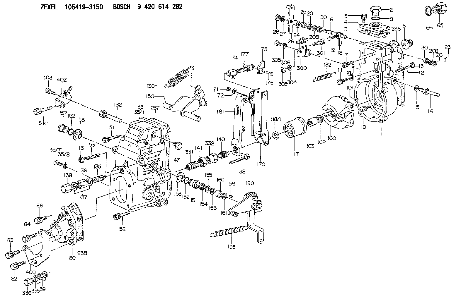
| 1. | [1] | 154004-5620 | GOVERNOR HOUSING |
| 2. | [1] | 154007-2900 | CAPSULE |
| 3. | [1] | 154390-2000 | GASKET |
| 4. | [1] | 154063-7900 | COVER |
| 5. | [4] | 020006-1640 | BLEEDER SCREW M6P1L16 4T |
| 6. | [1] | 154007-0200 | ADAPTOR |
| 7. | [1] | 020018-1840 | BLEEDER SCREW M8P1.25L18 |
| 8. | [1] | 029632-5070 | O-RING |
| 9. | [1] | 154350-1800 | PLATE |
| 10. | [5] | 029010-6810 | BLEEDER SCREW |
| 11. | [1] | 020106-1640 | BLEEDER SCREW M6P1.0L14 |
| 12. | [1] | 154010-1100 | FLAT-HEAD SCREW |
| 13. | [2] | 154011-0100 | HEXAGON NUT |
| 13. | [2] | 154011-0100 | HEXAGON NUT |
| 14. | [1] | 154013-2320 | BLEEDER SCREW |
| 15. | [1] | 014110-8440 | LOCKING WASHER |
| 16. | [1] | 155004-3301 | LEVER SHAFT |
| 18. | [1] | 155003-2520 | CONTROL LEVER |
| 19. | [1] | 155006-0700 | BLEEDER SCREW |
| 20. | [1] | 139308-0900 | PLAIN WASHER D16&8T1 |
| 20. | [1] | 139308-0900 | PLAIN WASHER D16&8T1 |
| 20B. | [1] | 139308-1000 | PLAIN WASHER D16&8T1.5 |
| 20B. | [1] | 139308-1000 | PLAIN WASHER D16&8T1.5 |
| 23. | [1] | 025520-1210 | SPLIT PIN |
| 24. | [1] | 154206-5200 | BUSHING |
| 25. | [1] | 154328-0500 | COILED SPRING |
| 26. | [1] | 154383-2420 | CONTROL LEVER |
| 27. | [1] | 014110-8440 | LOCKING WASHER |
| 28. | [1] | 013020-8040 | UNION NUT M8P1.25H7 |
| 30. | [2] | 029620-8050 | PACKING RING |
| 30. | [2] | 029620-8050 | PACKING RING |
| 35. | [1] | 154501-1120 | GOVERNOR COVER |
| 35/1. | [1] | 154501-1100 | GOVERNOR COVER |
| 35/7. | [1] | 154222-2700 | FLAT-HEAD SCREW |
| 35/8. | [1] | 014110-3440 | LOCKING WASHER |
| 38. | [1] | 154031-4700 | FLAT-HEAD SCREW |
| 39. | [1] | 139208-0400 | UNION NUT |
| 47. | [1] | 154036-1200 | CAPSULE |
| 51. | [1] | 139006-7100 | BLEEDER SCREW |
| 51C. | [1] | 020106-5040 | BLEEDER SCREW |
| 53. | [1] | 154010-0100 | FLAT-HEAD SCREW |
| 56. | [4] | 020106-3840 | BLEEDER SCREW |
| 65. | [1] | 153020-5220 | STOPPING DEVICE |
| 66. | [1] | 026518-2240 | GASKET D21.9&18.2T1 |
| 80. | [1] | 154064-4200 | COVER |
| 82. | [1] | 029020-6260 | BLEEDER SCREW |
| 83. | [1] | 029020-6260 | BLEEDER SCREW |
| 84. | [1] | 020006-2040 | BLEEDER SCREW M6P1L20 4T |
| 86. | [1] | 020006-1640 | BLEEDER SCREW M6P1L16 4T |
| 100. | [1] | 154101-0020 | FLYWEIGHT ASSEMBLY |
| 101. | [1] | 025803-1610 | WOODRUFF KEY |
| 102. | [1] | 029321-2020 | LOCKING WASHER |
| 103. | [1] | 029231-2030 | UNION NUT |
| 117. | [1] | 154123-2320 | SLIDING PIECE |
| 118/1. | [0] | 029311-0010 | SHIM D14&10.1T0.2 |
| 118/1. | [0] | 029311-0180 | SHIM D14&10.1T0.3 |
| 118/1. | [0] | 029311-0190 | SHIM D14&10.1T0.40 |
| 118/1. | [0] | 029311-0210 | SHIM D14&10.1T1 |
| 118/1. | [0] | 139410-0000 | SHIM D14.0&10.1T0.5 |
| 118/1. | [0] | 139410-0100 | SHIM D14.0&10.1T1.5 |
| 118/1. | [0] | 139410-3000 | SHIM D14&10.1T2.0 |
| 118/1. | [0] | 139410-3100 | SHIM D14&10.1T3.0 |
| 118/1. | [0] | 139410-3200 | SHIM D14&10.1T4.0 |
| 130. | [1] | 154150-6400 | GOVERNOR SPRING |
| 132. | [1] | 154154-0701 | COILED SPRING |
| 135. | [1] | 154158-0920 | HEADLESS SCREW |
| 136. | [1] | 029201-2140 | UNION NUT |
| 137. | [1] | 026512-1540 | GASKET D15.4&12.2T1.50 |
| 138. | [1] | 154159-1200 | CAP NUT |
| 140. | [1] | 154185-1320 | HEADLESS SCREW |
| 141. | [1] | 029201-6080 | UNION NUT |
| 150. | [1] | 154200-6920 | SWIVELLING LEVER |
| 151. | [1] | 154204-3000 | BUSHING |
| 152. | [2] | 029631-8020 | O-RING |
| 152. | [2] | 029631-8020 | O-RING |
| 153. | [2] | 016010-1640 | LOCKING WASHER |
| 153. | [2] | 016010-1640 | LOCKING WASHER |
| 154. | [1] | 139611-0000 | PACKING RING |
| 155. | [1] | 139411-0000 | SHIM |
| 156. | [0] | 029311-1070 | SHIM D16&11T0.5 |
| 157. | [1] | 154204-3100 | BUSHING |
| 159. | [1] | 025803-1310 | WOODRUFF KEY |
| 160. | [1] | 154206-2800 | BUSHING |
| 161. | [0] | 154206-0200 | PLAIN WASHER D19.5&11.2T1.0 |
| 170. | [1] | 154218-5220 | FORK LEVER |
| 171. | [1] | 016010-0540 | LOCKING WASHER |
| 172. | [4] | 029310-5170 | SHIM D8&5.3T0.5 |
| 174. | [1] | 154234-4020 | STRAP |
| 175. | [1] | 154232-3000 | CONNECTOR |
| 176. | [1] | 154222-5800 | BEARING PIN |
| 177. | [1] | 155402-3800 | SAFETY PIN |
| 181. | [1] | 154239-5120 | TENSIONING LEVER |
| 182. | [1] | 154237-1100 | BEARING PIN |
| 190. | [1] | 154396-3120 | CONTROL LEVER |
| 195. | [1] | 154314-2600 | COILED SPRING |
| 236. | [1] | 154390-1300 | GASKET |
| 237. | [1] | 154390-0300 | GASKET |
| 238. | [1] | 154390-5000 | GASKET |
| 300. | [1] | 154359-1320 | BRACKET |
| 301. | [1] | 020118-1640 | BLEEDER SCREW |
| 303. | [1] | 154011-1100 | UNION NUT |
| 304. | [1] | 029300-8320 | SHIM |
| 305. | [1] | 154010-6100 | BLEEDER SCREW |
| 306. | [1] | 014110-8440 | LOCKING WASHER |
| 331. | [1] | 154188-4520 | HEADLESS SCREW |
| 332. | [1] | 029201-6010 | UNION NUT |
| 335. | [2] | 026508-1140 | GASKET D11.4&8.2T1 |
| 336. | [1] | 154035-2000 | CAP NUT |
| 400. | [1] | 154376-3000 | BRACKET |
| 402. | [1] | 154376-3120 | BRACKET |
| 403. | [1] | 020006-1240 | BLEEDER SCREW M6P1L12 4T |
Include in #1:
101402-9632
as GOVERNOR
Cross reference number
Zexel num
Bosch num
Firm num
Name
Information:
Emergency Stop Push Button
Emergency Stop Push Button (ESPB)The Emergency Stop Push Button (ESPB) requires resetting both the push button and the air inlet shutoff (if equipped) before the engine will start.
Always determine the cause of the engine shutdown. Make necessary repairs before attempting restarting the engine.Emergency shutoff controls are for EMERGENCY use ONLY. DO NOT use Emergency shutoff devices or controls for normal stopping procedure. Refer to the Engine Stopping section of this manual for normal stopping procedures.
Oil Pressure Switch
Typical example of oil pressure switches, mounted in the rear of the junction box.An oil pressure switch has wires connected to the electrical shutoff system for alarm or shutdown functions. The oil pressure switch senses oil pressure at the bearing oil gallery. Switches may close at 48 to 62 kPa (7 to 9 psi) below actual trip point. No resetting procedure is required.Water Temperature Contactor Switch
This contactor switch is a coolant temperature sensor.The water temperature contactor switch is located near the coolant water regulator housing. Excessive water temperature closes the switch. Maximum coolant temperature to trip shutoff is 104°C (219°F). The switch opens as the coolant cools. No resetting procedure is required. The unit has wires connected to the electrical shutoff system for alarm or shutdown functions.
The sensing element must be submerged in the coolant to operate. Be sure to have an adequate water supply in the jacket water system, or engine damage could result.
Coolant Loss Sensor (If Equipped)
The optional coolant loss sensor is usually mounted near the top of the engine expansion tank or radiator. The sensor detects when the coolant level is below a preset minimum level.
This coolant loss switch, shown next to a sight glass, is mounted on the side of a radiator.If the coolant level drops below the minimum level, the sensor may sound an alarm, or cause a shutdown to avoid engine overheating or possible engine damage. Coolant must be added to the radiator or expansion tank to clear or reset the condition. In the event of intermittent engine shutdowns, the coolant water level should be checked. Add premixed coolant water to the fill tank, to within 13 mm (1/2 inch) below the filler tube.Check the expansion tank or radiator daily for proper coolant level.Overspeed Shutoffs
The electrical shutoff for the overspeed switch uses a magnetic pickup mounted in the flywheel housing. The electrical shutoff works through the fuel shutoff solenoid and air inlet shutoff (if equipped).
Magnetic pickup (1), mounted in the flywheel housing (2).Should the engine overspeed, the magnetic pickup will sense the excess speed. If overspeed is sensed, the electrical shutoff closes the air and fuel shutoff solenoids (the fuel rack will move to fuel OFF position).The overspeed shutdown has to be reset. Reset the air inlet shutoff (if equipped) and the overspeed switch. Both switches are located in the junction box or control panel.
Overspeed Shutoff Switch (Electro-Mechanical)This switch is mounted either on the tachometer drive or the governor. Excessive engine speed closes the switch by centrifugal force.If equipped with a Caterpillar Generator