Information governor
BOSCH
9 420 611 193
9420611193
ZEXEL
105419-2550
1054192550
ISUZU
8971705220
8971705220
Rating:
Scheme ###:
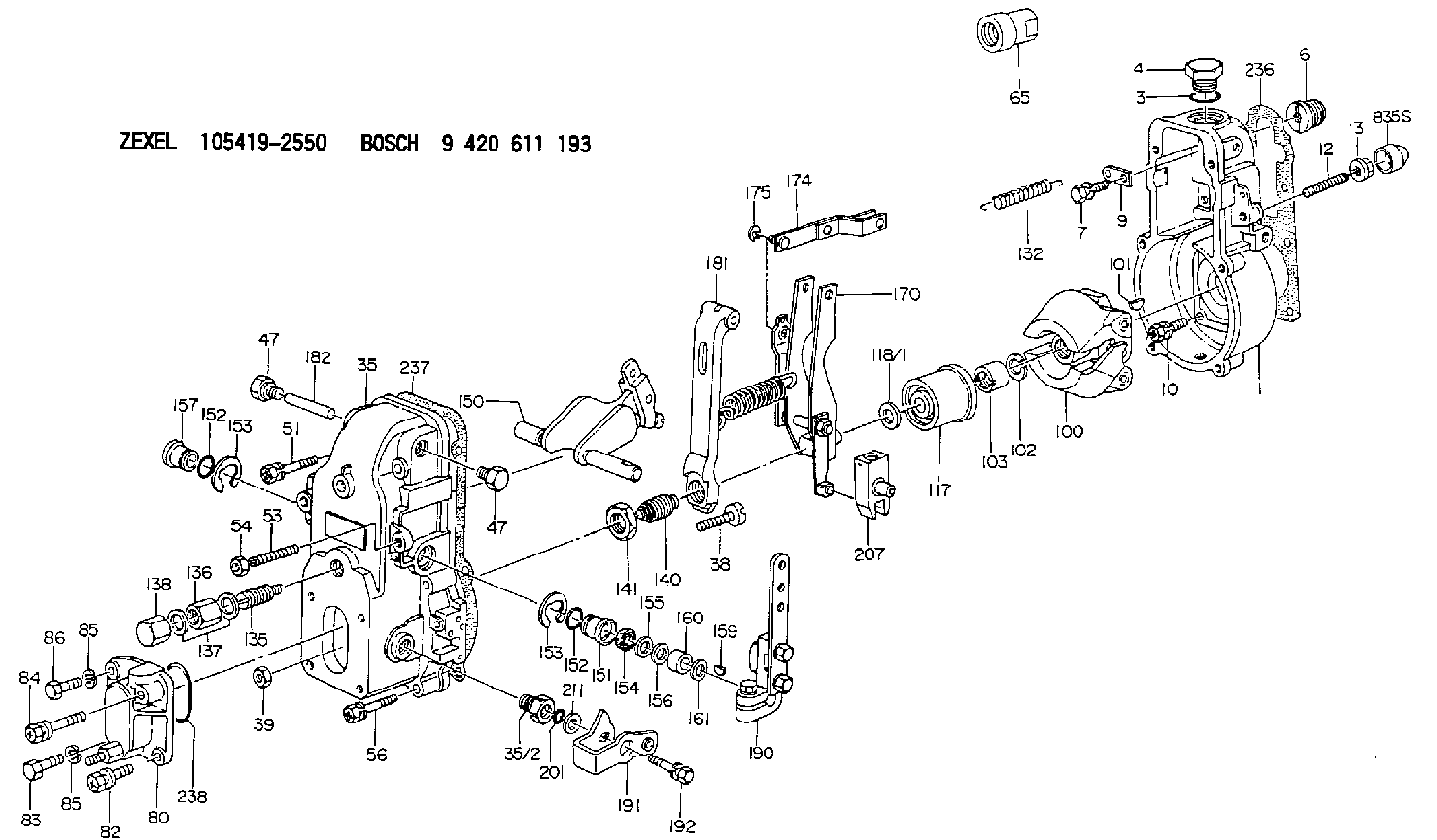
| 1. | [1] | 154000-6400 | GOVERNOR HOUSING |
| 3. | [1] | 029632-5070 | O-RING |
| 4. | [1] | 154007-2900 | CAPSULE |
| 6. | [1] | 154007-0200 | ADAPTOR |
| 7. | [1] | 020018-1840 | BLEEDER SCREW M8P1.25L18 |
| 9. | [1] | 154350-1900 | PLATE |
| 10. | [6] | 029010-6810 | BLEEDER SCREW |
| 12. | [1] | 154013-4000 | FLAT-HEAD SCREW |
| 13. | [1] | 154011-0100 | HEXAGON NUT |
| 35. | [1] | 154500-3020 | GOVERNOR COVER |
| 35/2. | [1] | 154321-0400 | BUSHING |
| 38. | [1] | 154031-0100 | FLAT-HEAD SCREW |
| 39. | [1] | 013020-6020 | UNION NUT M6P1H5 |
| 47. | [2] | 154036-0300 | CAPSULE |
| 47. | [2] | 154036-0300 | CAPSULE |
| 51. | [2] | 020106-5040 | BLEEDER SCREW |
| 53. | [1] | 154010-0100 | FLAT-HEAD SCREW |
| 54. | [1] | 154011-4900 | UNION NUT |
| 56. | [4] | 020106-3840 | BLEEDER SCREW |
| 65. | [1] | 155404-0200 | CAP |
| 80. | [1] | 154060-1020 | COVER |
| 82. | [1] | 154062-5001 | BLEEDER SCREW |
| 83. | [1] | 020006-1640 | BLEEDER SCREW M6P1L16 4T |
| 84. | [1] | 154062-5101 | BLEEDER SCREW |
| 85. | [2] | 014110-6440 | LOCKING WASHER |
| 85. | [2] | 014110-6440 | LOCKING WASHER |
| 86. | [1] | 020006-1640 | BLEEDER SCREW M6P1L16 4T |
| 100. | [1] | 154100-8520 | FLYWEIGHT ASSEMBLY |
| 101. | [1] | 025803-1610 | WOODRUFF KEY |
| 102. | [1] | 029321-2020 | LOCKING WASHER |
| 103. | [1] | 029231-2030 | UNION NUT |
| 117. | [1] | 154123-0120 | SLIDING PIECE |
| 118/1. | [0] | 029311-0010 | SHIM D14&10.1T0.2 |
| 118/1. | [0] | 029311-0180 | SHIM D14&10.1T0.3 |
| 118/1. | [0] | 029311-0190 | SHIM D14&10.1T0.40 |
| 118/1. | [0] | 029311-0210 | SHIM D14&10.1T1 |
| 118/1. | [0] | 139410-0000 | SHIM D14.0&10.1T0.5 |
| 118/1. | [0] | 139410-0100 | SHIM D14.0&10.1T1.5 |
| 118/1. | [0] | 139410-3000 | SHIM D14&10.1T2.0 |
| 118/1. | [0] | 139410-3100 | SHIM D14&10.1T3.0 |
| 118/1. | [0] | 139410-3200 | SHIM D14&10.1T4.0 |
| 132. | [1] | 154154-0800 | COILED SPRING |
| 135. | [1] | 154158-0920 | HEADLESS SCREW |
| 136. | [1] | 154011-2700 | UNION NUT |
| 137. | [2] | 026512-1540 | GASKET D15.4&12.2T1.50 |
| 138. | [1] | 154159-1200 | CAP NUT |
| 140. | [1] | 154178-9220 | HEADLESS SCREW |
| 141. | [1] | 029201-6010 | UNION NUT |
| 150. | [1] | 154200-7220 | SWIVELLING LEVER |
| 151. | [1] | 154204-3000 | BUSHING |
| 152. | [2] | 029631-8020 | O-RING |
| 152. | [2] | 029631-8020 | O-RING |
| 153. | [2] | 016010-1640 | LOCKING WASHER |
| 153. | [2] | 016010-1640 | LOCKING WASHER |
| 154. | [1] | 139611-0000 | PACKING RING |
| 155. | [1] | 139411-0000 | SHIM |
| 156. | [0] | 029311-1070 | SHIM D16&11T0.5 |
| 157. | [1] | 154204-3100 | BUSHING |
| 159. | [1] | 025803-1310 | WOODRUFF KEY |
| 160. | [1] | 154206-2800 | BUSHING |
| 161. | [0] | 154206-0200 | PLAIN WASHER D19.5&11.2T1.0 |
| 170. | [1] | 154210-7420 | FORK LEVER |
| 174. | [1] | 154230-3920 | STRAP |
| 175. | [1] | 016010-0540 | LOCKING WASHER |
| 181. | [1] | 154239-1720 | TENSIONING LEVER |
| 182. | [1] | 154237-0100 | BEARING PIN |
| 190. | [1] | 154342-9720 | CONTROL LEVER |
| 191. | [1] | 154367-7520 | CONTROL LEVER |
| 192. | [1] | 020006-1640 | BLEEDER SCREW M6P1L16 4T |
| 201. | [1] | 029631-0030 | O-RING &9.8W2.3 |
| 207. | [1] | 154326-5120 | CONTROL LEVER |
| 211. | [0] | 029311-0220 | SHIM D18&10.3T0.2 |
| 211B. | [0] | 029311-0230 | SHIM D18&10.3T0.5 |
| 236. | [1] | 154390-0000 | GASKET |
| 237. | [1] | 154390-0300 | GASKET |
| 238. | [1] | 029635-2020 | O-RING |
Include in #1:
101402-7100
as GOVERNOR
Cross reference number
Zexel num
Bosch num
Firm num
Name
Information:
You must read and understand the warnings and instructions contained in the Safety section of this manual before performing any operation or maintenance procedures.Before proceeding with this maintenance interval, perform previous maintenance interval requirements. Perform the maintenance at the interval listed in the Maintenance Schedule for your engine.Engine Protection Devices
Inspect For Proper Operation
The engine protective alarm and shutoff controls must be tested, inspected and checked by an authorized Caterpillar dealer at least every year or 1000 hours for proper operation. The manual shutoff functions should be tested to ensure proper operation and protection to the engine. Refer to Engine Control, Monitoring and Protection in the Operation Section in this Manual.Have the checks made by a qualified mechanic. Consult your authorized Caterpillar engine dealer, or refer to the Service Manual for your engine.Verify Alarm and Shutdown Operation
Check for loose, broken, or damaged wiring or components. Check the condition of all sensors and wiring. Repair or replace any broken or malfunctioning sensors before they become a problem. The inspection only takes a few minutes and could avert a potential problem that could cause your engine to fail.Operational Checks
Start the engine. Use the starting procedure found in the Engine Starting topic in this publication.The operational checks are intended to check the engine starting and stopping, lubrication and fuel systems as well as overall operation. The checks should take no longer than five minutes to complete. Longer periods of operation are not required.Automatic Switches
Check that all switches are in proper position for automatic start.The shutoff controls must be checked so that they function properly when they are required. To prevent damage to the engine while performing the test, only authorized personnel or your Caterpillar dealer should perform the checks.Engine Valve Lash
Check/Adjust
Initial valve lash adjustment on new or rebuilt engines is recommended and should have been performed at the first normally scheduled oil change interval (125 Hours) due to initial wear and seating of valve train components. Subsequent adjustments should be made at every 1000 Hours.Set the valve lash clearance to the nominal value given in the chart shown in the Engine Specifications section. Refer to the information in the Every 125 Hour maintenance and the Service Manual for the procedure.Turbochargers
If the engine is operated until the component(s) fails, it could cause additional damage to the engine. Damage to the turbocharger compressor wheel could cause parts from the compressor wheel to enter the engine cylinder and cause additional damage to the piston, valve and cylinder head.Inspect for Proper Operation
Turbocharger bearing failures can cause large quantities of oil to enter the air inlet and exhaust systems. Loss of engine lubricant can result in serious engine damage.Minor leakage of a turbocharger housing under extended low idle operation will not cause problems as long as no turbocharger bearing failure occurred.When a turbocharger bearing failure is accompanied by a significant engine performance loss (exhaust smoke or engine speed up at no load), DO NOT continue engine operation until the turbocharger is repaired or replaced.
1. Remove the