Information governor
BOSCH
9 420 611 191
9420611191
ZEXEL
105419-2500
1054192500
ISUZU
1157709340
1157709340
Rating:
Scheme ###:
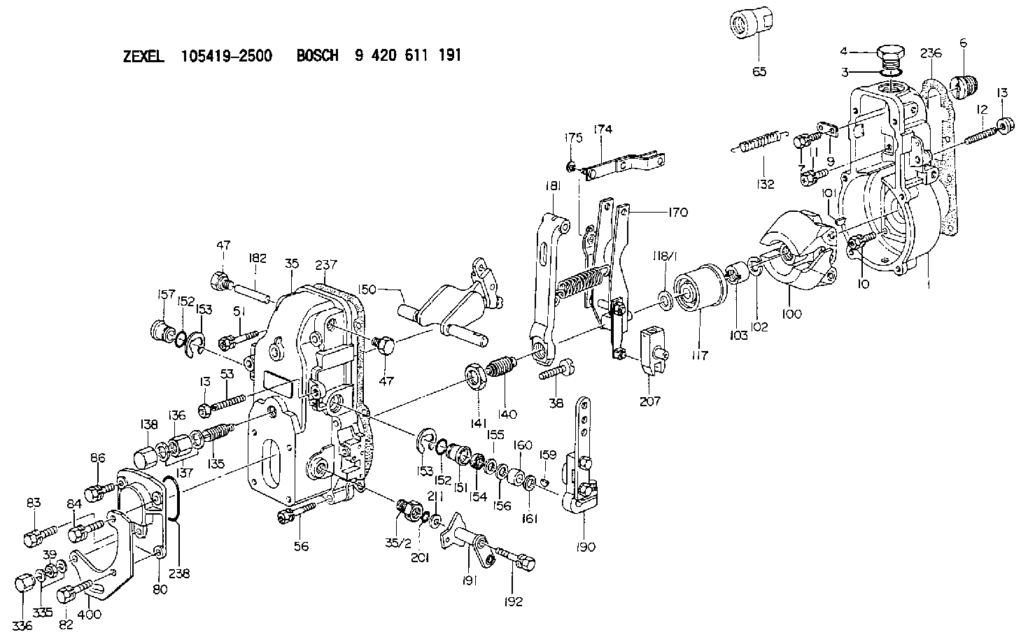
| 1. | [1] | 154000-6400 | GOVERNOR HOUSING |
| 3. | [1] | 029632-5070 | O-RING |
| 4. | [1] | 154007-2900 | CAPSULE |
| 6. | [1] | 154007-0200 | ADAPTOR |
| 7. | [1] | 020018-1840 | BLEEDER SCREW M8P1.25L18 |
| 9. | [1] | 154350-1800 | PLATE |
| 10. | [5] | 029010-6810 | BLEEDER SCREW |
| 11. | [1] | 020106-1640 | BLEEDER SCREW M6P1.0L14 |
| 12. | [1] | 154010-1100 | FLAT-HEAD SCREW |
| 13. | [2] | 154011-0100 | HEXAGON NUT |
| 13. | [2] | 154011-0100 | HEXAGON NUT |
| 35. | [1] | 154500-3020 | GOVERNOR COVER |
| 35/2. | [1] | 154321-0400 | BUSHING |
| 38. | [1] | 154031-2400 | FLAT-HEAD SCREW |
| 39. | [1] | 139206-0600 | UNION NUT |
| 47. | [2] | 154036-0300 | CAPSULE |
| 47. | [2] | 154036-0300 | CAPSULE |
| 51. | [2] | 020106-5040 | BLEEDER SCREW |
| 53. | [1] | 154010-0200 | FLAT-HEAD SCREW |
| 56. | [4] | 020106-3840 | BLEEDER SCREW |
| 65. | [1] | 154050-6120 | STOPPING DEVICE |
| 80. | [1] | 154063-1400 | COVER |
| 82. | [1] | 020006-2040 | BLEEDER SCREW M6P1L20 4T |
| 83. | [1] | 020006-2040 | BLEEDER SCREW M6P1L20 4T |
| 84. | [1] | 029020-6260 | BLEEDER SCREW |
| 86. | [1] | 020006-1640 | BLEEDER SCREW M6P1L16 4T |
| 100. | [1] | 154101-0120 | FLYWEIGHT |
| 101. | [1] | 025803-1610 | WOODRUFF KEY |
| 102. | [1] | 029321-2020 | LOCKING WASHER |
| 103. | [1] | 029231-2030 | UNION NUT |
| 117. | [1] | 154123-0120 | SLIDING PIECE |
| 118/1. | [0] | 029311-0010 | SHIM D14&10.1T0.2 |
| 118/1. | [0] | 029311-0180 | SHIM D14&10.1T0.3 |
| 118/1. | [0] | 029311-0190 | SHIM D14&10.1T0.40 |
| 118/1. | [0] | 029311-0210 | SHIM D14&10.1T1 |
| 118/1. | [0] | 139410-0000 | SHIM D14.0&10.1T0.5 |
| 118/1. | [0] | 139410-0100 | SHIM D14.0&10.1T1.5 |
| 118/1. | [0] | 139410-3000 | SHIM D14&10.1T2.0 |
| 118/1. | [0] | 139410-3100 | SHIM D14&10.1T3.0 |
| 118/1. | [0] | 139410-3200 | SHIM D14&10.1T4.0 |
| 132. | [1] | 154154-1200 | COILED SPRING |
| 135. | [1] | 154158-1320 | HEADLESS SCREW |
| 136. | [1] | 154011-1700 | UNION NUT |
| 137. | [2] | 026512-1540 | GASKET D15.4&12.2T1.50 |
| 138. | [1] | 154159-1200 | CAP NUT |
| 140. | [1] | 154176-5620 | HEADLESS SCREW |
| 141. | [1] | 029201-6010 | UNION NUT |
| 150. | [1] | 154200-6920 | SWIVELLING LEVER |
| 151. | [1] | 154204-3000 | BUSHING |
| 152. | [2] | 029631-8020 | O-RING |
| 152. | [2] | 029631-8020 | O-RING |
| 153. | [2] | 016010-1640 | LOCKING WASHER |
| 153. | [2] | 016010-1640 | LOCKING WASHER |
| 154. | [1] | 139611-0000 | PACKING RING |
| 155. | [1] | 139411-0000 | SHIM |
| 156. | [0] | 029311-1070 | SHIM D16&11T0.5 |
| 157. | [1] | 154204-3100 | BUSHING |
| 159. | [1] | 025803-1310 | WOODRUFF KEY |
| 160. | [1] | 154206-2800 | BUSHING |
| 161. | [0] | 154206-0200 | PLAIN WASHER D19.5&11.2T1.0 |
| 170. | [1] | 154218-3920 | FORK LEVER |
| 174. | [1] | 154230-3920 | STRAP |
| 175. | [1] | 016010-0540 | LOCKING WASHER |
| 181. | [1] | 154239-0520 | TENSIONING LEVER |
| 182. | [1] | 154237-0100 | BEARING PIN |
| 190. | [1] | 154342-9720 | CONTROL LEVER |
| 191. | [1] | 154381-5820 | CONTROL LEVER |
| 192. | [1] | 020006-4040 | BLEEDER SCREW |
| 201. | [1] | 029631-0030 | O-RING &9.8W2.3 |
| 207. | [1] | 154326-5120 | CONTROL LEVER |
| 211. | [0] | 029311-0220 | SHIM D18&10.3T0.2 |
| 211B. | [0] | 029311-0230 | SHIM D18&10.3T0.5 |
| 236. | [1] | 154390-0000 | GASKET |
| 237. | [1] | 154390-0300 | GASKET |
| 238. | [1] | 029635-2020 | O-RING |
| 335. | [2] | 026506-1040 | GASKET D9.9&6.2T1 |
| 336. | [1] | 154035-1600 | CAP NUT |
| 400. | [1] | 154374-4300 | BRACKET |
Include in #1:
101602-8360
as GOVERNOR
Cross reference number
Zexel num
Bosch num
Firm num
Name
Information:
Proper operation and maintenance are key factors in obtaining the maximum life and economy of the engine. Normal operating temperatures are between -40°C (-40°F) and 120°C (248°F). Following the directions in this Manual will lower operating costs.The time needed for the engine to reach the normal mode of operation is usually less than the time taken for a walk-around inspection of the engine.After the engine is started and the cold low speed operation is completed, the engine can be operated at rated speed and low power. The engine will reach normal operating temperature faster when operated at low power demand than when idled at no load. Typically the engine should reach operating temperature in a few minutes.The electronic governor/control (ECM) system provides complete engine speed governing and controls cold start mode strategies, torque shaping, smoke limiting, system diagnostics and communication data links to monitor performance and diagnostic information. Warning outputs are provided for low oil pressure, low boost pressure, high coolant temperature and low coolant level with a diagnostic lamp.Electronic Control System Operation
The 3408 & 3412 electronically controlled governor functions like a mechanical governor in the mid-speed operating range. The governor has a programmable low idle rpm of 600 to 750 rpm, regardless of load. The governor eliminates most of the overrun at high idle that is experienced with a mechanical governor.During the cranking cycle, the safety shutoffs are inoperative, and will not allow a low oil pressure shut down. When oil pressure reaches a safe level, the safety circuit is armed by the arming relay. High water temperature or low oil pressure will now stop the engine and prevent major damage.If an unsafe engine condition exists, a sending unit completes the circuit to the safety relay and locking relay. The safety relay closes the fuel supply valve and the engine stops. The locking relay insures that the circuit to the safety relay is complete, even if the remote contacts open.Before restarting any unit which has been shut down by the safety circuit, the cause must be determined and corrected. The safety circuit must be reset by moving the start selector switch to the OFF position.Operating Driven Equipment Without Load
* Operate the engine at LOW IDLE. After normal oil pressure is reached and the jacket water temperature gauge begins to rise, the engine may be operated at full load.* If equipped with auxiliary driven equipment: To get the driven equipment in motion, use a smooth, easy engagement without increasing engine speed above low idle or slipping the clutch. Engage the clutch smoothly. It is not necessary to advance the throttle to get the driven equipment moving in most instances.
DO NOT allow the engine rpm to exceed 2450 rpm, or engine damage could result.Operation of the engine at 2450 rpm or above will cause the DIAGNOSTIC lamp to come on and a fault to be logged.
Operating Driven Equipment With Load
Always increase engine speed before increasing load.
1. Move the governor control lever to half engine speed. Begin operating the engine