Information governor
BOSCH
9 420 611 516
9420611516
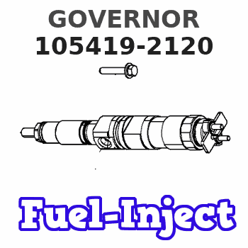
ZEXEL
105419-2120
1054192120
ISUZU
8971379260
8971379260
Rating:
Scheme ###:
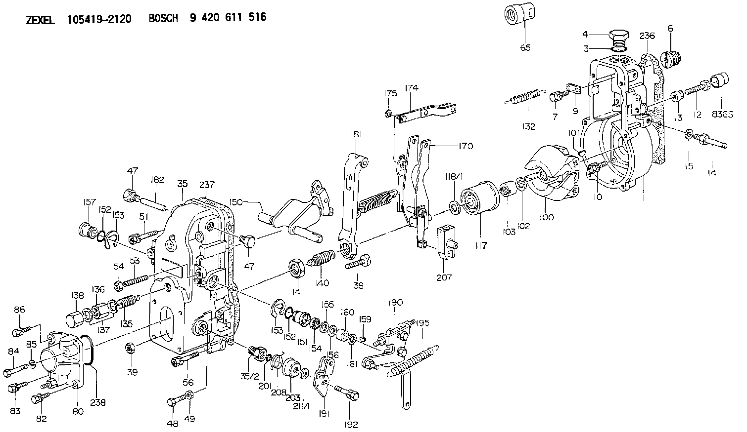
| 1. | [1] | 154000-6400 | GOVERNOR HOUSING |
| 3. | [1] | 029632-5070 | O-RING |
| 4. | [1] | 154007-2900 | CAPSULE |
| 6. | [1] | 154007-0200 | ADAPTOR |
| 7. | [1] | 020018-1840 | BLEEDER SCREW M8P1.25L18 |
| 9. | [1] | 154350-1900 | PLATE |
| 10. | [6] | 029010-6810 | BLEEDER SCREW |
| 12. | [1] | 154010-8100 | BLEEDER SCREW M8P1.25L65 |
| 12B. | [1] | 154010-8900 | BLEEDER SCREW M8P1.25L67.5 |
| 13. | [1] | 154011-0100 | HEXAGON NUT |
| 14. | [1] | 154012-1500 | BLEEDER SCREW |
| 15. | [1] | 014110-8440 | LOCKING WASHER |
| 35. | [1] | 154500-3720 | GOVERNOR COVER |
| 35/2. | [1] | 154321-0400 | BUSHING |
| 38. | [1] | 154031-0100 | FLAT-HEAD SCREW |
| 39. | [1] | 013020-6020 | UNION NUT M6P1H5 |
| 47. | [2] | 154036-0300 | CAPSULE |
| 47. | [2] | 154036-0300 | CAPSULE |
| 48. | [1] | 154037-0700 | BLEEDER SCREW |
| 49. | [1] | 154038-0200 | HEXAGON NUT |
| 51. | [2] | 020106-5040 | BLEEDER SCREW |
| 53. | [1] | 154010-0200 | FLAT-HEAD SCREW |
| 54. | [1] | 154011-2300 | UNION NUT |
| 56. | [4] | 020106-3840 | BLEEDER SCREW |
| 65. | [1] | 155404-0200 | CAP |
| 80. | [1] | 154063-1220 | COVER |
| 82. | [1] | 029020-6210 | BLEEDER SCREW |
| 83. | [1] | 029020-6210 | BLEEDER SCREW |
| 84. | [1] | 010006-3840 | BLEEDER SCREW |
| 85. | [1] | 014110-6440 | LOCKING WASHER |
| 86. | [1] | 020006-1640 | BLEEDER SCREW M6P1L16 4T |
| 100. | [1] | 154101-0020 | FLYWEIGHT ASSEMBLY |
| 101. | [1] | 025803-1610 | WOODRUFF KEY |
| 102. | [1] | 029321-2020 | LOCKING WASHER |
| 103. | [1] | 029231-2030 | UNION NUT |
| 117. | [1] | 154123-0120 | SLIDING PIECE |
| 118/1. | [0] | 029311-0010 | SHIM D14&10.1T0.2 |
| 118/1. | [0] | 029311-0180 | SHIM D14&10.1T0.3 |
| 118/1. | [0] | 029311-0190 | SHIM D14&10.1T0.40 |
| 118/1. | [0] | 029311-0210 | SHIM D14&10.1T1 |
| 118/1. | [0] | 139410-0000 | SHIM D14.0&10.1T0.5 |
| 118/1. | [0] | 139410-0100 | SHIM D14.0&10.1T1.5 |
| 118/1. | [0] | 139410-3000 | SHIM D14&10.1T2.0 |
| 118/1. | [0] | 139410-3100 | SHIM D14&10.1T3.0 |
| 118/1. | [0] | 139410-3200 | SHIM D14&10.1T4.0 |
| 132. | [1] | 154154-0800 | COILED SPRING |
| 135. | [1] | 154158-0920 | HEADLESS SCREW |
| 136. | [1] | 154011-2700 | UNION NUT |
| 137. | [2] | 026512-1540 | GASKET D15.4&12.2T1.50 |
| 138. | [1] | 154159-1200 | CAP NUT |
| 140. | [1] | 154178-9220 | HEADLESS SCREW |
| 141. | [1] | 029201-6010 | UNION NUT |
| 150. | [1] | 154200-7220 | SWIVELLING LEVER |
| 151. | [1] | 154204-3000 | BUSHING |
| 152. | [2] | 029631-8020 | O-RING |
| 152. | [2] | 029631-8020 | O-RING |
| 153. | [2] | 016010-1640 | LOCKING WASHER |
| 153. | [2] | 016010-1640 | LOCKING WASHER |
| 154. | [1] | 139611-0000 | PACKING RING |
| 155. | [1] | 139411-0000 | SHIM |
| 156. | [0] | 029311-1070 | SHIM D16&11T0.5 |
| 157. | [1] | 154204-3100 | BUSHING |
| 159. | [1] | 025803-1310 | WOODRUFF KEY |
| 160. | [1] | 154206-2800 | BUSHING |
| 161. | [0] | 154206-0200 | PLAIN WASHER D19.5&11.2T1.0 |
| 170. | [1] | 154210-7420 | FORK LEVER |
| 174. | [1] | 154230-3920 | STRAP |
| 175. | [1] | 016010-0540 | LOCKING WASHER |
| 181. | [1] | 154239-1720 | TENSIONING LEVER |
| 182. | [1] | 154237-0100 | BEARING PIN |
| 190. | [1] | 154349-5920 | CONTROL LEVER |
| 191. | [1] | 154380-5320 | CONTROL LEVER |
| 192. | [1] | 020006-1640 | BLEEDER SCREW M6P1L16 4T |
| 195. | [1] | 154314-2600 | COILED SPRING |
| 201. | [1] | 029631-0030 | O-RING &9.8W2.3 |
| 203. | [1] | 154322-0100 | CAP |
| 207. | [1] | 154326-5120 | CONTROL LEVER |
| 208. | [1] | 154327-7300 | COILED SPRING |
| 211/1. | [0] | 029311-0520 | SHIM D20.8&10.3T0.2 |
| 211/1. | [0] | 029311-0530 | SHIM D20.8&10.3T0.25 |
| 211/1. | [0] | 029311-0540 | SHIM D20.8&10.3T0.3 |
| 211/1. | [0] | 029311-0550 | SHIM D20.8&10.3T0.35 |
| 211/1. | [0] | 029311-0560 | SHIM D20.8&10.3T0.4 |
| 211/1. | [0] | 029311-0570 | SHIM D20.8&10.3T0.5 |
| 236. | [1] | 154390-0000 | GASKET |
| 237. | [1] | 154390-0300 | GASKET |
| 238. | [1] | 029635-2020 | O-RING |
Cross reference number
Zexel num
Bosch num
Firm num
Name
105419-2120
8971379260 ISUZU
GOVERNOR
K 14JB MECHANICAL GOVERNOR GOV RSV GOV
K 14JB MECHANICAL GOVERNOR GOV RSV GOV
Information:
Flush
8. Refill the cooling system with clean water mixed with the proper concentration (six to ten percent) of Fast Acting-Type Caterpillar Cooling System Cleaner. Tighten cooling system vent cap. For proper cooling system maintenance cleaning, refer to label directions for the type of Caterpillar Cooling System Cleaner used in your cooling system.9. Start and run (operate) the engine to circulate fluid in the cooling system.10. Stop the engine and allow to cool. Loosen cooling system vent cap and drain plugs.11. Drain the cleaning solution. Flush the cooling system with clean water and a neutralizing solution until draining water is clear. Clean and install all drain plugs and/or close the drain valve. Sodium Carbonate crystals at a rate of 250 grams per 40 liters of water (1/2 pound per 10 U.S. gallon of water) may be used as a neutralizer. Repeat Steps 8 thru 11 if necessary until the draining water is clear.Install Thermostat
Caterpillar engines incorporate a shunt design cooling system and require operating the engine with a thermostat installed.If the thermostat is installed wrong, it will cause the engine to overheat.
Inspect gaskets before assembly and replace if worn or damaged.12. Install a new seal in the thermostat housing and install a new thermostat.13. Install a new gasket and the thermostat housing on the engine cylinder head.14. Install the cooling system connections and tighten the hose or piping clamps.Fill
All water is corrosive at engine operating temperature. The cooling system should be protected with cooling system conditioner at all times. Use Caterpillar liquid cooling system conditioner to treat the coolant mixture.
Refer to the Cooling System Specifications section of this publication for all information regarding about the appropriate maintenance of the cooling system or contact your Caterpillar dealer for assistance. See Refill Capacities chart in this publication for the capacity of your engine's system.15. Be certain all drain plugs are clean and installed. Mix a solution of acceptable water and Caterpillar Antifreeze (which contains supplemental coolant additive).16. Start and run the engine with the cooling system vent cap loosened. Operate the engine and allow the coolant to warm, the thermostats to open and the coolant level to stabilize. Inspect for leaks and proper operating temperature.
To prevent engine damage, never add coolant to an overheated engine. Allow the engine to cool first.
17. Add coolant mixture if necessary to bring the coolant to within 13 mm (1/2 inch) below the bottom of the fill tube or the correct level on the sight glass, if equipped. Upon initial fill the sight gauge can indicate an incorrect coolant level. Be sure the coolant is to the bottom of the fill tube. Recheck the coolant level and fill the cooling system to the bottom of the fill tube if the system was low.
In cold weather, frequently check the specific gravity of the coolant solution to ensure adequate protection.If the engine is to be stored in, or shipped to an area with freezing temperatures, the cooling system must be either protected to the lowest expected outside temperature