Information governor
BOSCH
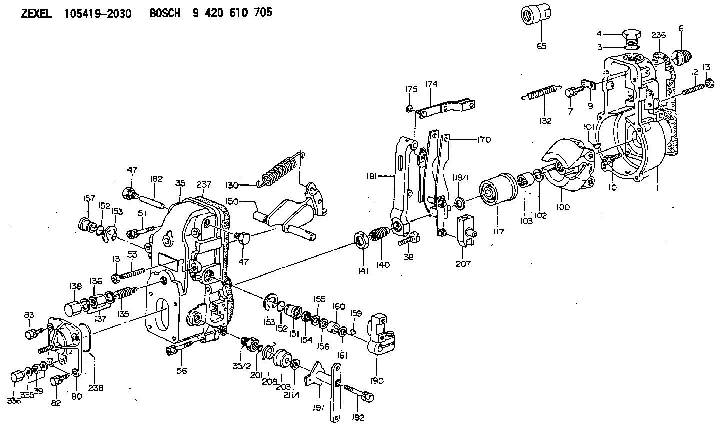
9 420 610 705
9420610705
ZEXEL
105419-2030
1054192030
Rating:
Scheme ###:
| 1. | [1] | 154000-7000 | GOVERNOR HOUSING |
| 3. | [1] | 029632-5070 | O-RING |
| 4. | [1] | 154007-2900 | CAPSULE |
| 6. | [1] | 154007-0200 | ADAPTOR |
| 7. | [1] | 020018-1840 | BLEEDER SCREW M8P1.25L18 |
| 9. | [1] | 154350-1900 | PLATE |
| 10. | [6] | 029010-6810 | BLEEDER SCREW |
| 12. | [1] | 154010-1100 | FLAT-HEAD SCREW |
| 13. | [2] | 154011-0100 | HEXAGON NUT |
| 13. | [2] | 154011-0100 | HEXAGON NUT |
| 35. | [1] | 154500-5320 | GOVERNOR COVER |
| 35/2. | [1] | 154321-0400 | BUSHING |
| 38. | [1] | 154031-2400 | FLAT-HEAD SCREW |
| 39. | [1] | 139206-0600 | UNION NUT |
| 47. | [2] | 154036-0300 | CAPSULE |
| 47. | [2] | 154036-0300 | CAPSULE |
| 51. | [2] | 020106-5040 | BLEEDER SCREW |
| 53. | [1] | 154010-0200 | FLAT-HEAD SCREW |
| 56. | [4] | 020106-3840 | BLEEDER SCREW |
| 65. | [1] | 154050-6120 | STOPPING DEVICE |
| 80. | [1] | 154063-5420 | COVER |
| 82. | [2] | 029020-6210 | BLEEDER SCREW |
| 83. | [2] | 020006-1640 | BLEEDER SCREW M6P1L16 4T |
| 100. | [1] | 154101-0320 | FLYWEIGHT ASSEMBLY |
| 101. | [1] | 025803-1610 | WOODRUFF KEY |
| 102. | [1] | 029321-2020 | LOCKING WASHER |
| 103. | [1] | 029231-2030 | UNION NUT |
| 117. | [1] | 154123-2320 | SLIDING PIECE |
| 118/1. | [0] | 029311-0010 | SHIM D14&10.1T0.2 |
| 118/1. | [0] | 029311-0180 | SHIM D14&10.1T0.3 |
| 118/1. | [0] | 029311-0190 | SHIM D14&10.1T0.40 |
| 118/1. | [0] | 029311-0210 | SHIM D14&10.1T1 |
| 118/1. | [0] | 139410-0000 | SHIM D14.0&10.1T0.5 |
| 118/1. | [0] | 139410-0100 | SHIM D14.0&10.1T1.5 |
| 118/1. | [0] | 139410-3000 | SHIM D14&10.1T2.0 |
| 118/1. | [0] | 139410-3100 | SHIM D14&10.1T3.0 |
| 118/1. | [0] | 139410-3200 | SHIM D14&10.1T4.0 |
| 130. | [1] | 154150-0400 | GOVERNOR SPRING |
| 132. | [1] | 154154-1200 | COILED SPRING |
| 135. | [1] | 154158-1020 | HEADLESS SCREW |
| 136. | [1] | 154011-1700 | UNION NUT |
| 137. | [2] | 026512-1540 | GASKET D15.4&12.2T1.50 |
| 138. | [1] | 154159-1200 | CAP NUT |
| 140. | [1] | 154177-0920 | HEADLESS SCREW |
| 141. | [1] | 029201-6010 | UNION NUT |
| 150. | [1] | 154200-6920 | SWIVELLING LEVER |
| 151. | [1] | 154204-3000 | BUSHING |
| 152. | [2] | 029631-8020 | O-RING |
| 152. | [2] | 029631-8020 | O-RING |
| 153. | [2] | 016010-1640 | LOCKING WASHER |
| 153. | [2] | 016010-1640 | LOCKING WASHER |
| 154. | [1] | 139611-0000 | PACKING RING |
| 155. | [1] | 139411-0000 | SHIM |
| 156. | [0] | 029311-1070 | SHIM D16&11T0.5 |
| 157. | [1] | 154204-3100 | BUSHING |
| 159. | [1] | 025803-1310 | WOODRUFF KEY |
| 160. | [1] | 154206-2800 | BUSHING |
| 161. | [0] | 154206-0200 | PLAIN WASHER D19.5&11.2T1.0 |
| 170. | [1] | 154210-7420 | FORK LEVER |
| 174. | [1] | 154230-3920 | STRAP |
| 175. | [1] | 016010-0540 | LOCKING WASHER |
| 181. | [1] | 154236-4100 | TENSIONING LEVER |
| 182. | [1] | 154237-0100 | BEARING PIN |
| 190. | [1] | 154340-2020 | CONTROL LEVER |
| 191. | [1] | 154381-3920 | CONTROL LEVER |
| 192. | [1] | 020006-4540 | BLEEDER SCREW M6P1L45 |
| 201. | [1] | 029631-0030 | O-RING &9.8W2.3 |
| 203. | [1] | 154322-0100 | CAP |
| 207. | [1] | 154326-5120 | CONTROL LEVER |
| 208. | [1] | 154327-7300 | COILED SPRING |
| 211/1. | [0] | 029311-0520 | SHIM D20.8&10.3T0.2 |
| 211/1. | [0] | 029311-0530 | SHIM D20.8&10.3T0.25 |
| 211/1. | [0] | 029311-0540 | SHIM D20.8&10.3T0.3 |
| 211/1. | [0] | 029311-0550 | SHIM D20.8&10.3T0.35 |
| 211/1. | [0] | 029311-0560 | SHIM D20.8&10.3T0.4 |
| 211/1. | [0] | 029311-0570 | SHIM D20.8&10.3T0.5 |
| 236. | [1] | 154390-1300 | GASKET |
| 237. | [1] | 154390-0300 | GASKET |
| 238. | [1] | 029635-2020 | O-RING |
| 335. | [2] | 026506-1040 | GASKET D9.9&6.2T1 |
| 336. | [1] | 154035-1600 | CAP NUT |
Include in #1:
101605-9400
as GOVERNOR
Cross reference number
Zexel num
Bosch num
Firm num
Name
Information:
Alarm Contactors
The engine is equipped with standard electrical overspeed switch which uses a flywheel housing mounted magnetic pickup. The magnetic pickup will close the circuit and the alarm will be activated when the engine exceeds the setpoint rpm. This engine may be equipped with a Coolant Level Alarm contactor. An Oil Pressure and Coolant Temperature Alarm contactors are optional.Alarm switches are electrically connected to an indicator light, bell or horn. When an alarm is activated, it is an indication of a potential problem and corrective measures must be taken before the situation becomes an emergency. While these alarm switches do not stop the engine, the problem should be investigated and corrective action taken to prevent engine damage.The alarm will continue until the condition is corrected. Then the light will turn off and the bell or horn will be silenced.To silence the bell or horn while repairs are being made, a two-way switch and a red indicator light may be installed. The red indicator light will come on when the alarm is turned off. The red light will stay on, to indicate that the engine is NOT protected, if the switch is left in the OFF position after the repairs have been made.Low Oil Pressure Switch (Early Engines)
The switch will not protect the system from rapid oil loss, caused by failures such as line breakage.
Low oil pressure switchThis device is usually mounted on the side of the engine. The oil lines are connected to the switch. Low oil pressure closes the switch. To reset the switch, push the RESET button in the junction box until it latches. After the engine starts and develops oil pressure, the button will move to the extended (running) position.
The button must be in the RUN position to protect the engine. If the button remains in the OFF position, the engine oil pump may not be developing normal oil pressure and proper checks should be made.
Manually operated systems require resetting of this switch before starting. Automatic start-stop systems use a pressure switch which resets itself.Low Oil Pressure Switch (Later Engines)
This switch does NOT require resetting. This switch is mounted in the oil manifold on the side of the block with the oil lines connected to it. Low oil pressure opens this switch to disconnect the electrical circuit to the shutoff solenoid. This prevents the battery from continuously energizing the solenoid while the engine is stopped.This switch is also used with the electric governor. On start-up, oil pressure will close the switch to allow the electric governor to increase engine speed.Marine Transmission Oil Temperature Switch
The switch is typically located in the oil line between the oil pump and the oil strainer or the oil filter of the marine transmission.High Coolant Water Temperature Switch
Coolant level must be maintained in order for the alarm to function, because the sensing element must be submerged in the coolant to operate. The alarm cannot actuate if the coolant level is low.
The switch is located in the water temperature regulator housing. Excessive