Information governor
BOSCH
F 019 Z4E 577
f019z4e577
ZEXEL
105419-1851
1054191851
NISSAN-DIESEL
1910990361
1910990361
Rating:
Scheme ###:
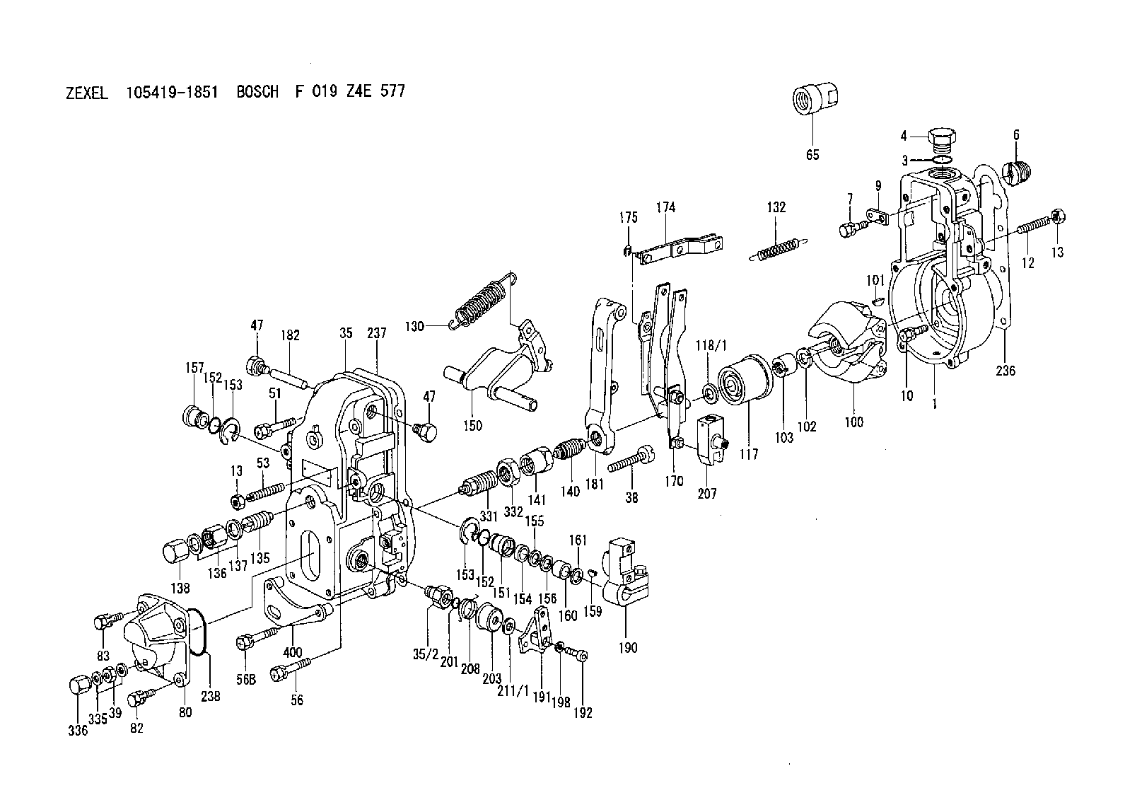
| 1. | [1] | 154000-6400 | GOVERNOR HOUSING |
| 3. | [1] | 029632-5070 | O-RING |
| 4. | [1] | 154007-2900 | CAPSULE |
| 6. | [1] | 154007-0200 | ADAPTOR |
| 7. | [1] | 020018-1840 | BLEEDER SCREW M8P1.25L18 |
| 9. | [1] | 154350-1900 | PLATE |
| 10. | [6] | 029010-6810 | BLEEDER SCREW |
| 12. | [1] | 154010-0100 | FLAT-HEAD SCREW |
| 13. | [2] | 154011-0100 | HEXAGON NUT |
| 13. | [2] | 154011-0100 | HEXAGON NUT |
| 35. | [1] | 154500-3020 | GOVERNOR COVER |
| 35/2. | [1] | 154321-0400 | BUSHING |
| 38. | [1] | 154031-3000 | FLAT-HEAD SCREW |
| 39. | [1] | 139206-0600 | UNION NUT |
| 47. | [2] | 154036-0300 | CAPSULE |
| 47. | [2] | 154036-0300 | CAPSULE |
| 51. | [2] | 020106-5040 | BLEEDER SCREW |
| 53. | [1] | 154010-0100 | FLAT-HEAD SCREW |
| 56. | [2] | 020106-3840 | BLEEDER SCREW |
| 56B. | [2] | 139006-8500 | BLEEDER SCREW |
| 65. | [1] | 154050-6120 | STOPPING DEVICE |
| 80. | [1] | 154064-0400 | COVER |
| 82. | [2] | 029020-6210 | BLEEDER SCREW |
| 83. | [2] | 020006-1640 | BLEEDER SCREW M6P1L16 4T |
| 100. | [1] | 154101-0520 | FLYWEIGHT |
| 101. | [1] | 025803-1610 | WOODRUFF KEY |
| 102. | [1] | 029321-2020 | LOCKING WASHER |
| 103. | [1] | 029231-2030 | UNION NUT |
| 117. | [1] | 154123-0120 | SLIDING PIECE |
| 118/1. | [0] | 029311-0010 | SHIM D14&10.1T0.2 |
| 118/1. | [0] | 029311-0180 | SHIM D14&10.1T0.3 |
| 118/1. | [0] | 029311-0190 | SHIM D14&10.1T0.40 |
| 118/1. | [0] | 029311-0210 | SHIM D14&10.1T1 |
| 118/1. | [0] | 139410-0000 | SHIM D14.0&10.1T0.5 |
| 118/1. | [0] | 139410-0100 | SHIM D14.0&10.1T1.5 |
| 118/1. | [0] | 139410-3000 | SHIM D14&10.1T2.0 |
| 118/1. | [0] | 139410-3100 | SHIM D14&10.1T3.0 |
| 118/1. | [0] | 139410-3200 | SHIM D14&10.1T4.0 |
| 130. | [1] | 154150-4100 | GOVERNOR SPRING |
| 132. | [1] | 154154-0500 | COILED SPRING |
| 135. | [1] | 154158-0920 | HEADLESS SCREW |
| 136. | [1] | 154011-1700 | UNION NUT |
| 137. | [2] | 026512-1540 | GASKET D15.4&12.2T1.50 |
| 138. | [1] | 154159-1200 | CAP NUT |
| 140. | [1] | 154185-3620 | HEADLESS SCREW |
| 141. | [1] | 029201-6080 | UNION NUT |
| 150. | [1] | 154200-7220 | SWIVELLING LEVER |
| 151. | [1] | 154204-4300 | BUSHING |
| 152. | [2] | 029631-8020 | O-RING |
| 152. | [2] | 029631-8020 | O-RING |
| 153. | [2] | 016010-1640 | LOCKING WASHER |
| 153. | [2] | 016010-1640 | LOCKING WASHER |
| 154. | [1] | 139611-0000 | PACKING RING |
| 155. | [1] | 139411-0000 | SHIM |
| 156. | [0] | 029311-1070 | SHIM D16&11T0.5 |
| 157. | [1] | 154204-4400 | BUSHING |
| 159. | [1] | 025803-1310 | WOODRUFF KEY |
| 160. | [1] | 154206-2800 | BUSHING |
| 161. | [0] | 154206-0200 | PLAIN WASHER D19.5&11.2T1.0 |
| 170. | [1] | 154210-7420 | FORK LEVER |
| 174. | [1] | 154230-3920 | STRAP |
| 175. | [1] | 016010-0540 | LOCKING WASHER |
| 181. | [1] | 154236-1500 | TENSIONING LEVER |
| 182. | [1] | 154237-0100 | BEARING PIN |
| 190. | [1] | 154340-2020 | CONTROL LEVER |
| 191. | [1] | 154364-7520 | CONTROL LEVER |
| 192. | [1] | 010206-1440 | HEX-SOCKET-HEAD CAP SCREW M6P1L14 |
| 198. | [1] | 029320-6010 | LOCKING WASHER |
| 201. | [1] | 029631-0030 | O-RING &9.8W2.3 |
| 203. | [1] | 154322-0100 | CAP |
| 207. | [1] | 154326-5120 | CONTROL LEVER |
| 208. | [1] | 154327-9900 | COILED SPRING |
| 211/1. | [0] | 029311-0520 | SHIM D20.8&10.3T0.2 |
| 211/1. | [0] | 029311-0530 | SHIM D20.8&10.3T0.25 |
| 211/1. | [0] | 029311-0540 | SHIM D20.8&10.3T0.3 |
| 211/1. | [0] | 029311-0550 | SHIM D20.8&10.3T0.35 |
| 211/1. | [0] | 029311-0560 | SHIM D20.8&10.3T0.4 |
| 211/1. | [0] | 029311-0570 | SHIM D20.8&10.3T0.5 |
| 236. | [1] | 154390-0000 | GASKET |
| 237. | [1] | 154390-0300 | GASKET |
| 238. | [1] | 029635-2020 | O-RING |
| 331. | [1] | 154172-3420 | HEADLESS SCREW |
| 332. | [1] | 029201-6010 | UNION NUT |
| 335. | [2] | 026506-1040 | GASKET D9.9&6.2T1 |
| 336. | [1] | 154035-1600 | CAP NUT |
| 400. | [1] | 154371-9620 | BRACKET |
Include in #1:
101481-9371
as GOVERNOR
Cross reference number
Zexel num
Bosch num
Firm num
Name
105419-1851
1910990361 NISSAN-DIESEL
GOVERNOR
A K 14JB MECHANICAL GOVERNOR GOV RSV GOV
A K 14JB MECHANICAL GOVERNOR GOV RSV GOV
Information:
Cold Weather Battery Maintenance
General Maintenance
1. After adding make-up water, charge the battery. The added water could dilute the electrolyte enough without charging to cause freezing and permanent damage to the battery.2. Keep the batteries fully charged either by operating the charging system or by using a battery charger.3. Keep the battery warm when not in use. In an unheated area, the heat from a lighted electric bulb is usually sufficient.
Use only a shop cord with a heavy wire guard around the light bulb.
Do not lay a lighted bulb directly on a battery case; the heat at point of contact could melt the battery case.Do not lay cloth or flammable material in contact with a lighted bulb; charring and/or fire could result.4. Use starting aids as instructed for starting the engine.5. Use booster batteries as required. Connect the batteries as instructed below.6. If a battery is not going to be used for a period of time, be sure the battery is fully charged while stored. Use a battery hydrometer to check the specific gravity of each cell, and use a battery charger to keep the battery charged. See the instructions below.Voltage Test (After Load)
A load test should be made on a battery that discharges very rapidly when in use. To do this apply a resistance of three times the ampere/hour rating of the battery across the battery main terminals. Allow the resistance to discharge the the battery for 15 seconds and immediately test the battery voltage. A 6 volt battery in good condition will test 4.5 volts; a 12 volt battery in good condition will test 9 volts and a 24 volt battery will test 18 volts.Starter
No periodic service is indicated for the electric starter brushes between general reconditioning periods. The brushes should only be inspected after removal of the starter from the engine and removal of the commutator end bearing frame. The electric starter commutator end and drive end bearings are equipped with wicks for lubrication purposes. The wicks should be saturated with oil whenever the electric starter is removed or disassembled.It is suggested that cleaning and reconditioning be entrusted to your authorized dealer.Pinion Clearance Adjustment
Whenever the solenoid is installed, the pinion clearance should be adjusted. The adjustment should be made with the starting motor removed.Bench test and adjust the pinion clearance at installation of solenoid as follows:
CIRCUIT FOR CHECKING AND ADJUSTING PINION CLEARANCE1. Install the solenoid without connector from the MOTOR terminal on solenoid to the motor.2. Connect a battery, of the same voltage as the solenoid, to the terminal marked SW.3. Connect the other side of battery to ground terminal or to solenoid frame.
ADJUSTING PINION CLEARANCE4. MOMENTARILY flash a jumper wire from the solenoid terminal marked MOTOR to the frame or ground terminal. The pinion will shift into cranking position and will remain there until the battery is disconnected.5. Push pinion towards commutator end to eliminate free movement.6. Pinion clearance should be .36 in. (9.14 mm).7. Adjust clearance by removing plug and turning shaft nut.
ADJUSTING PINION